AS/NZS 5033:2021 Update – What You Need to Know
As part of the solar industry, you’re probably accustomed to the 2014 version of the standard, which had two amendments published in 2018. In November 2021, this standard was updated to reflect the rapid growth of this industry and provide updated safety practices. Knowledge is power, and these changes could impact your business as you transition over to the new standard.
This standard is now the current version, but installers and designers will need to check with their state regulator to determine if they will be enacting a transition period of six months from the date of publishing as stated within the standard. During the transition period, installers and designers can opt to use AS/NZS 5033:2014 or AS/NZS 5033:2021, but not parts of each. The updated version of the standard can be purchased from Standards Australia, SAI Global or Techstreet.
What’s new in the 2021 PV array installation and safety requirements standard?
To start, the 2021 version of this standard is slightly longer than the previous 2014 version at 142 pages compared to 125. Although that may seem tedious to read, the 2021 version has addressed this concern with a more reader friendly and simplified layout. Many of the extra pages come in the form of extended appendices which provide helpful examples and explanations useful for understanding the standard. In addition, several clauses have been removed, rewritten or restructured to reflect this new approach.
Why are these changes necessary? In short, the updated standard aims to tackle key issues which have arisen due to technology changes and shifting industry expectations since the previous version. The most important changes for designers and installers are:
- Scope of the standard
- Maximum system voltage
- PV circuit current calculations
- Changes to d.c. rooftop isolator requirements
- Disconnection points
- Conductor sizing and selection
- Installation of cables in the ceiling space
- Other cable and DC isolator installation changes
- Signage and documentation
1. Scope of the Standard
These changes impact most PV designers and installers in commercial and residential spaces. Businesses working in the PV sector would also be affected by this standard
The scope of the AS/NZS 5033:2021 has broadened. Previously, AS/NZS 5033:2014 did not cover arrays larger than 240 kW (although the general requirements were typically still applied to projects of this size), nor arrays less than 240 W and 50 V in portable equipment.
Clause 1.1 has removed the >240 kW exception and instead states that the standard does not apply to PV arrays on large-scale ground mounted PV power plants with restricted access to personnel and connected to dedicated high voltage systems. However, it is noted that the standard should still be used as guidance in the absence of other standards.
The lower extent of the scope has been reduced so that the standard does not apply to PV arrays less than 100 W and less than 35 V open circuit at STC, but this is no longer limited to portable devices. The standard also does not apply to PV arrays in transportable structures, vehicles and boats.
What this means for you
Designers and installers who work on PV systems larger than 240 kW that are not utility scale solar plants, are now required to comply with the full standard. Most companies in this space would have been already applying the requirements of AS/NZS 5033:2014 to their projects, but the ability to vary commercial- and industrial-scale PV designs based on engineering justification has been removed, except where explicitly permitted by AS/NZS 5033:2021.
Designers and installers involved with PV arrays on transportable structures and vehicles (e.g. campervans, food trucks, demountables, mobile road signs) are no longer required to abide by AS/NZS 5033:2021, but should refer to AS/NZS 3001 instead. Designers and installers involved with PV arrays on boats are no longer required to abide by AS/NZS 5033:2021, but should refer to AS/NZS 3004 instead.
2. Maximum System Voltage
Domestic PV systems are growing in demand and size, and the recent update has reflected these changing conditions. Maximum allowable system voltage has persisted at 600 V for domestic dwelling systems since 2014, limiting design choices for designers. The revision of maximum system voltage has provided more design choices and ensured future proofing for the standard going forward. However, the ability to install domestic systems greater than 600 V is not yet able to be implemented due to a conflict with AS/NZS 4777.1:2016.
Updated Clauses:
- Maximum voltage limits (Clause 3.1)
- PV d.c. circuit maximum voltage calculation (Clause 4.2.1.3)
What has changed?
Clause 3.1 has increased the maximum PV array voltage from 600 V.d.c. to 1000 V.d.c. for domestic systems. It has also introduced a 1500 V.d.c. maximum PV array voltage limit for other installations; previously no limit applied. The term ‘’domestic dwelling” has been dropped and replaced by “domestic electrical installation” broadening the application for this standard to a wider range of buildings. Unfortunately, electrical regulators have determined that this change does not override Clause 2.3 in AS/NZS 4777.1:2016, which also specifies a 600 V.d.c. limit for systems in domestic dwellings. Therefore, designers and installers are not able to install systems over 600 V.d.c. in houses or apartment blocks until AS/NZS 4777.1 is updated or amended.
It is important for designers and installers to note that the PV array maximum voltage (now called maximum voltage of PV d.c. circuits) is still a temperature adjusted voltage, meaning that it is calculated based on the lowest expected operating temperature at the installation site. This is not changed from AS/NZS 5033:2014, but it is a common oversight particularly when documented at the Fire Emergency Information sign.
Clause 4.2.1.3 also updated calculations for the PV array maximum voltage where the array is either partially or fully optimised. AS/NZS 5033:2021 refers to these configurations as “systems containing partial DCUs” and “systems containing DCUs on all modules” respectively, where “DCU” stands for d.c. Conditioning Unit, aka module level power electronics or d.c. optimisers. The PV array maximum voltage is now equal to the maximum DCU voltage output multiplied by the number of DCUs in series, plus the temperature-adjusted maximum voltage of any non-optimised PV modules in the same string. However, the clause also permits calculation of the PV array maximum voltage in accordance with IEC 62548 which may increase design flexibility for fully optimised systems such as SolarEdge. DCU manufacturers will be able to provide specific information on calculations for their products.
3. PV Circuit Current Calculations
The calculation of maximum current in a circuit is critical to the correct sizing of the circuit conductors and any overcurrent protection. AS/NZS 5033:2021 has made major changes to the formulas used for current calculations, but this is primarily re-organisation and clarification rather than substantive alterations to component sizing.
Updated Clauses:
- Calculation of maximum string current (Clause 3.3.3.1)
- Calculation of potential string fault current (Clause 3.3.3.2)
- Calculation of potential sub-array fault current (Clause 3.3.3.3)
- Requirements for overcurrent protection (Clause 3.3.4)
- Nominal overcurrent protection rating calculations (Clause 3.3.5)
- PV d.c. circuit current calculations (Clause 4.4.2)
What has changed?
Rather than basing overcurrent device sizing and cable current carrying capacity directly on ISC_MOD (short circuit current of the PV module) with various other factors, AS/NZS 5033:2021 now defines maximum string current (Clause 3.3.3.1) and potential string/sub-array fault current (Clauses 3.3.3.2 and 3.3.3.3) in terms of ISTRING MAX and bases equipment sizing on these (Clauses 3.3.4, 3.3.5 and 4.4.2).
Therefore, although from a brief glance the clauses look different with adjusted notations, the calculated end result should only be different from AS/NZS 5033:2014 if bi-facial modules, DCUs, or inverters with backfeed potential are being used. The addition of a d.c. current rating adjustment factor for bi-facial modules (KI), detailed in Appendix J, reflects the increased irradiation available to this type of module.
A new term IBF TOTAL has been defined, as the sum of all backfeed sources of current other than the PV modules. When determining whether string overcurrent protection is required, as per Clause 3.3.4.1, the total backfeed current must be added to the potential fault current from the PV strings, prior to checking whether the value is greater than the reverse current rating of the PV module. This change will only affect you if the PV inverter or solar controller you use has a backfeed current. Most grid-connect PV inverters do not have backfeed current, but you will find this in the inverter manual (not datasheet).
Further changes also occurred in Clause 3.3.5 with regards to the maximum current rating for overcurrent protection, with the removal of the redundant 2.4x upper limit. The nominal rating for the overcurrent protection must still be less than or equal to the current carrying capacity of the relevant cable, and if installed at the string level, less than or equal to the reverse current rating of the PV module or DCU.
Designers/installers should be aware that the notations of these formulas have been updated, but the changes will not affect calculations for most system designs.
4. Changes to D.C. Rooftop Isolator Requirements
Note: additional requirements around disconnection points, wiring locations and signage apply if a rooftop isolator is not used.
In recent years, it has become apparent that d.c. isolators are a common point of failure in rooftop PV systems. To address this, the requirements for d.c. isolators have been altered to ensure a more appropriate use of isolators when necessary.
The change in d.c. isolator requirement provides more flexibility to designers and installers given appropriate safety measures are taken.
Updated Clauses:
- PV isolation methods (Clause 4.3.3)
- PV isolation methods for systems exceeding 120 V (Clause 4.3.3.1)
- PV Isolation methods for systems not exceeding 120 V (Clause 4.3.3.2)
What has changed?
Installers and designers need to be aware of the adjustments to the clauses to stay compliant and reduce the need for unnecessary components. According to Clause 4.3.3 of the standard, rooftop d.c. isolators are no longer required for all systems. However, installers and designers need to comply with the additional requirements around disconnection points, wiring locations and signage that have been introduced in place of the rooftop isolator requirements.
For systems using microinverters
There are no major changes to isolator requirements. A d.c. isolator is not required if the inverter and PV module are within 1.5 metres, and the input to the inverter doesn’t exceed 120 V. Rooftop a.c. isolator requirements are specified in AS/NZS 4777.1.
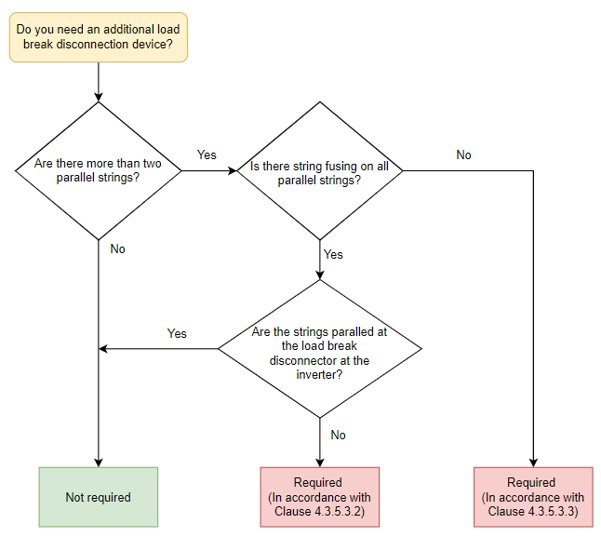
For systems with only 1 or 2 strings in parallel
An isolator (load break disconnection device) is no longer required adjacent to the PV array. It has been replaced with a “disconnection point” (see below). An isolator is still required adjacent to or integrated with the inverter, with the same sizing requirements as Amendment 2 of AS/NZS 5033:2014.
For systems with more than 2 strings in parallel that have string fusing on every string
A d.c. isolator (load break disconnection device) is required at the point where the strings are paralleled together. A standard combiner box with integrated fusing and switch disconnector should meet this requirement, providing the devices are appropriately rated.
For systems with more than 2 strings in parallel without string fusing
In this case, a d.c. isolator is required at the point where the strings are paralleled together, such that when it is turned off, there are no more than 2 strings in parallel. It may be difficult to find an appropriately rated isolator for this situation. In this case an isolator at the inverter is required to be separate to the inverter.
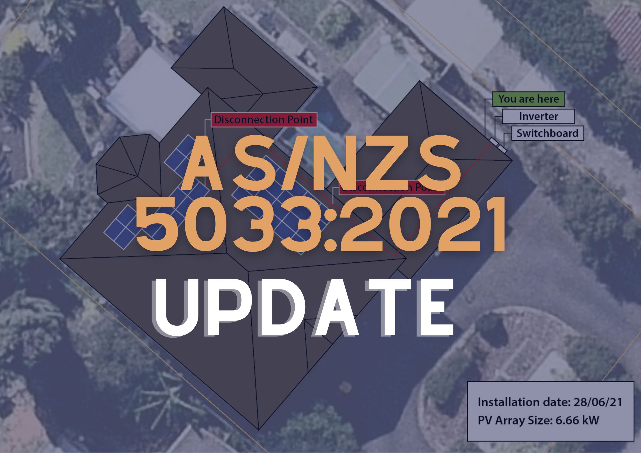
5. Disconnection Points
“Disconnection point” is a new term defined in AS/NZS 5033:2021, and is essentially the replacement for rooftop isolators in most situations. It’s a form of non-load breaking disconnection and will commonly be implemented as the plug-and-socket connectors that come preinstalled on most PV modules. To comply as a disconnection point, there are a few additional requirements for these connectors (see Clause 4.3.5.2.1). The main changes that will require a change in installation practices are:
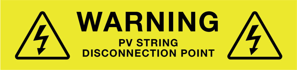
- The PV module or structure must be labelled with “WARNING: PV String Disconnection Point” within 300mm of the disconnection point to show the disconnection point’s location. (see Figure A.4(d) in AS/NZS 5033:2021)
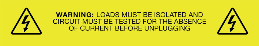
- The cables of the positive and negative connectors must both be labelled with a sign ““WARNING: LOADS MUST BE ISOLATED AND CIRCUIT MUST BE TESTED FOR ABSENCE OF CURRENT BEFORE UNPLUGGING” and the signs must be within 100 mm of the connectors.
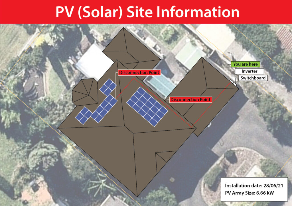
- They must be documented on the PV (Solar) Site Information Sign (see below).
- The positive and negative connectors must be located together.
- The connectors must not be more than 150mm from the edge of the PV module that they are installed under.
- They must be readily available i.e. reachable for inspection, maintenance or repairs without needing to dismantle structural parts.
- New considerations for cable installation in the ceiling space (see below).
Clause 4.3.3.1 allows for a load break disconnection device to be installed adjacent to the PV modules, in lieu of a disconnection point – i.e. using a rooftop isolator instead of the new disconnection point rules.
Updated Clauses:
- Disconnection point (Clause 1.3.11)
- PV isolation methods (Clause 4.3.3)
- Disconnection point (Clause 4.3.5.2.1)
6. Conductor Sizing and Selection
Conductor sizing and selection can not only impact the performance and cost of a system but are critical to safe operation of the system. The new standard has amended the previous minimum conductor sizing due to changing industry requirements. Maximum allowable voltage drop has also been updated to allow more flexible system design and installations.
Updated Clauses:
- Selection of cables: General (Clause 4.4.2.1)
- Conductor size (Clause 4.4.2.3)
- Voltage drop (Clause 4.4.2.4)
- Underground cables (Clause 4.4.2.5)
- Earthing or bonding conductor size (4.6.5)
What has changed?
A minimum conductor cross-sectional area of 4 mm2 has been introduced for both PV d.c. cables (compulsory requirement as per Clause 4.4.2.3) and earth conductors (recommendation as per Clause 4.6.5). Clause 4.6.5 also introduces additional earth conductor sizing considerations based on the type of inverter installed and the nature of the a.c. electrical installation.
Designers working with commercial- and industrial-scale systems will need to familiarise themselves with Table 4.6, since it may require substantial upsizing of earth cables relative to the AS/NZS 5033:2014 requirements. For non-separated inverters with powered neutral (i.e. most transformerless inverters), the d.c. earth conductor must be at least as large as the d.c. active conductor, and as per Table 5.1 of AS/NZS 3000 with respect to the inverter a.c. active conductor:
| Size of a.c. active conductor (mm2) | Minimum size of d.c. earth conductor (mm2) |
|---|---|
| Up to and including 10 | 4 |
| 16 and 25 | 6 |
| 35 | 10 |
| 50 | 16 |
| 70 and 95 | 25 |
| 120 | 35 |
Designers familiar with Table 4.2 from AS/NZS 5033:2014 will notice a change in notation in AS/NZS 5033:2021; however as mentioned above, this will not affect the current carrying capacity calculations for most systems.
Clause 4.4.2.4 has introduced a maximum allowable d.c. voltage drop to a permissible value of 5% for systems greater than 120 V. This does not replace the familiar value of 3% from AS/NZS 5033:2014 – the recommendation of a 3% voltage drop limit has been shifted from Clause 2.1.10 in the 2014 version to Clause 2.2.3 in the 2021 version but retained in full. Designers need to be aware that the 5% limit in Clause 4.4.2.4 is a compulsory requirement (denoted by “shall”) while the 3% limit in Clause 2.2.3 is a recommendation.
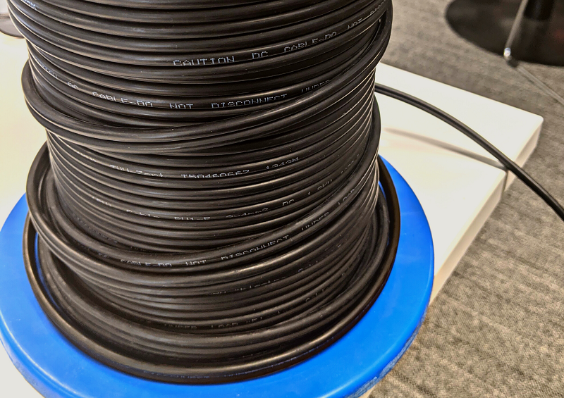
In terms of cable specifications, PV d.c. cables must be double insulated where the PV d.c. circuit maximum voltage is above 35V instead of the previous LV requirement. Cables installed in a functionally earthed system or in a system with a non-separated inverter (i.e. most grid connected PV systems) are now explicitly required to have their conductor-to-earth d.c. voltage rating greater than or equal to the PV d.c. circuit maximum voltage. Furthermore, PV1-F compliance is no longer a requirement, instead PV d.c. cables must conform to IEC 62930 if installed above ground and a relevant standard for underground cables if not.
The cable sizing methodology referenced in AS/NZS 5033 is covered in detail by AS/NZS 3008.1.1, which has been updated for 2025 with dedicated DC tables and revised HF-110 values — read our full update here.
7. Installation of Cables in the Ceiling Space
To accompany the removal of rooftop isolators, there are increased restrictions for where and how PV cables are installed in the ceiling space. These requirements are implemented to reduce the chances of cables collapsing below the ceiling in the event of a ceiling collapse.
Updated Clauses:
- Wiring enclosures for the wiring system (Clause 4.4.5.2)
What are the changes?
The PV cables are now classified into 4 sections:
- Between the PV modules and the disconnection point
- Between the disconnection point and the load break disconnection device
- Between the load break disconnection device and the inverter
- Between non-adjacent groups of PV modules
In general, the ceiling space installation requirements for cables between the isolator and inverter have not changed. This means that if a rooftop isolator is installed, installers should not need to make changes to their ceiling space installation practices.
If there is no rooftop isolator, there are increased restrictions on where cables can be installed in the ceiling space. These rules apply to the cable section between the disconnection point and the load break disconnection device (isolator) and between non-adjacent groups of PV modules.
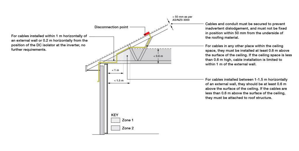
- Cables and conduit must be secured to prevent inadvertent dislodgement, and must not be fixed in position within 50 mm from the underside of the roofing material.
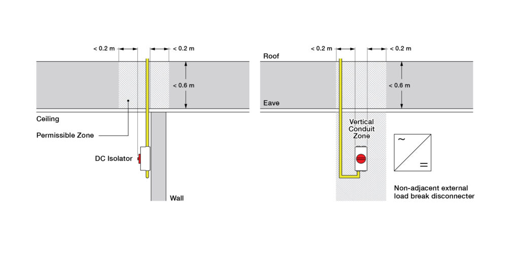
- For cables installed within 1 m horizontally of an external wall or 0.2 m horizontally from the position of the DC isolator at the inverter, no further requirements.
- For cables installed between 1-1.5 m horizontally of an external wall, they should be at least 0.6 m above the surface of the ceiling. If the cables are less than 0.6 m above the surface of the ceiling, they must be attached to roof structure.
- For cables in any other place within the ceiling space, they must be installed at least 0.6 m above the surface of the ceiling. If the ceiling space is less than 0.6 m high, cable installation is limited to within 1 m of the external wall.
- If the roof space is accessible, or the cables are installed in an accessible floor space, signage is required as specified below.
8. Other Cable and D.C. Isolator Installation Changes
The AS/NZS 5033:2021 update includes a number of new or updated requirements with respect to installation of cables and d.c. isolators. Notable changes that installers should be aware of include:
- d.c. isolator enclosure and mounting. Clause 4.3.5.3.1 introduces new requirements for load break disconnection devices – these apply to the d.c. isolator at the inverter as well as the rooftop isolator if one is installed. The isolator must be either mounted on 0.2 mm or thicker metal shroud, inside a 0.2 mm or thicker metal enclosure, or mounted on a non-combustible surface or barrier material that extends at least 200 mm either side. If it has penetrations through a surface that protects against spread of fire, the hole must be sealed with fire retardant sealant. The isolator must also be installed external to the building (this does not include the isolator required at the inverter). See Clause 4.5.3 for requirements on the isolator at the inverter.
- Weather protection of d.c. isolators. The requirement for isolators to be protected from direct sunlight and weather has been quantified in Clause 4.4.7.3. An imaginary line is drawn at a 30 degree angle from the edge of the roof eaves, balcony edge or shroud, and the isolator must be installed fully within this zone. Appendix K demonstrates these protection requirements for the isolators, and examples of acceptable shrouding can be seen below.
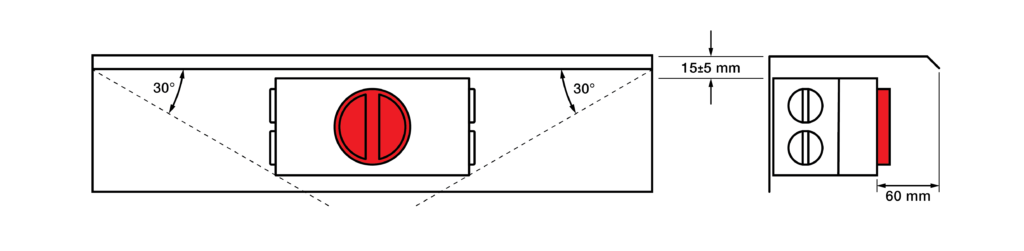
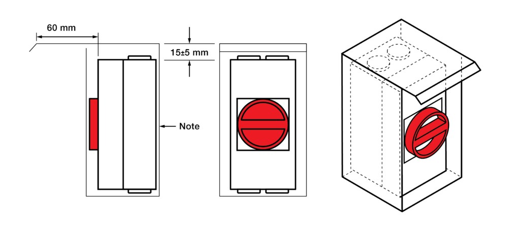
Figure 7. Minimum clearance for a shroud for a vertically mounted d.c. isolator: See Appendix K3 in AS/NZS 5033:2021
- d.c. isolator enclosures. Clause 4.4.6.2 now requires enclosures containing disconnection devices to have pressure equalisation valves fitted into the enclosure or integrated into other equipment within 300 mm. Dedicated individual enclosures must be rated to AS 60947.3, as was the case in Amendment 2 of AS/NZS 5033:2014, but enclosures for assemblies or circuit breakers must now conform to IEC 61439-1 and IEC 61439-2, and be rated to at least IP56 if installed outdoors.
- Enclosures containing conductor terminations. Clause 4.4.6 requires enclosures containing conductor terminations to be rated at a minimum of IPXXB and IP2X. If containing conductor terminations and exposed outdoors then the enclosure must be rated at IP55 minimum. Likewise, cable glands exposed to outdoor environments must be IP56 minimum. Note: ‘enclosures containing conductor terminations’ includes d.c. isolators but does not include inverters for the purposes of this clause.
- Entries/exit of enclosures containing conductor terminations. Clause 4.4.7.2.1 now allows top-entry for the cable between one indoor isolator and an adjacent indoor inverter or another adjacent indoor isolator. This change albeit small provides a bit more flexibility to installers. Clause 4.4.7.2.2 requires cable gland entries or exits in outdoor environments to include a drip loop, and if the entry or exit is from the side face of the enclosure, then the gland must be within a 30 degree area from the edge of the roof eaves, balcony edge or shroud. According to Clause 4.4.7.2.3, if an outdoor conduit section terminates into an enclosure containing conductor terminations, even if the enclosure is indoors, the open ends of the conduit must be sealed with a gland that complies with the outdoor environment requirements (Clause 4.4.7.2.2). If the conduit termination is into an enclosure containing a disconnection device, an IP56 drain device is required at the lowest point of the conduit system. The requirements in these clauses also apply to cable entries into inverters, if the inverter is exposed to weather as per Clause 4.4.7.2.1.
- Restricted access to PV d.c. cables. Where PV d.c. cables are installed external to the building, Clause 4.4.5.2.2 requires that they have restricted access, either by being in a restricted access location or by being installed in a wiring enclosure. However, 300 mm of unprotected cable is still permitted at the inverter or d.c. isolator, and the AS/NZS 5033:2014 limit of 600 V for this exception has now been removed. Installers are permitted to have a maximum of 300 mm of unprotected PV d.c. cable at the inverter or DC isolator as long as the location is not subject to mechanical damage.
- Lightning protection system (LPS) and surge protection devices (SPDS). There were also amendments to the lightning protection system. Appendix G3 requires bonding if the structure of the LPS provides protection for the PV array. Adjustments to surge protection minimum specifications are prevalent in Appendix G4, but largely not important for residential installations.
9. Signage and Documentation
A variety of adjustments have been made to the signage and documentation section of AS/NZS 5033:2021. The main changes are as follows:
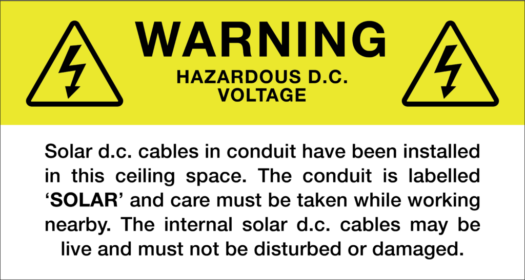
- A new warning sign for solar d.c. cable in accessible roof/floor space was added (Figure A.1).
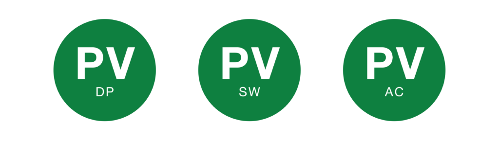
Clause 5.4 contains new fire and emergency information sign. Previously just a green reflective circle with the letters “PV” sufficed. Now the standard requires additional letters to identify the type of isolation method (microinverters(AC), disconnection point (DP) or load-break disconnection device (SW)) (Figure A.3) and must be placed on or immediately adjacent to the main metering panel and main switchboard. The “AC” denoted sign is only required for inverters where the PV d.c. circuit maximum voltage is less than 120 V d.c. at the inverter PV input, and the PV modules are within 1.5m of the inverter.
New labelling is required for disconnection points (Figure A.4(c) and A.4(d)). Figure A.4(c) must be placed within 100 mm of the disconnection point on both the positive and negative cable. Figure A.4(d) must be placed within 300mm of the disconnection point and be attached to the PV module or structure.
A new sign at the main switchboard and/or meter box is required to show the solar system layout. This will be a major change for designers/installers, as the details required on the sign are highly site-specific and may thus require a change in workplace procedure in order to finalise the details on the sign prior to installation day (Figure A.5).
The system manual is now required to include the disconnection device location and cable routing. Installers will be able to meet this requirement by including a copy of the solar system layout sign in the system manual paperwork.
If you are not confident with AS/NZS 5033:2021 or any other standards, let GSES do the heavy lifting. We can produce detailed designs tailored to your needs. Contact our design team at design@gses.com.au or click the button below.
FAQ
Here are some questions we’ve been asked so far on the standard changes. If you have a question that hasn’t been asked yet, feel free to use the form below and we’ll get back to you.
Q: What are the fault loop requirements in AS/NZS 3000 to meet the new DC earth sizing requirements on large roofs?
A: There are a couple of different locations in AS/NZS 3000 and a few different clauses that will have to be abided by. The first one is 0.5 Ohm maximum resistance from the earth bar to the furthest module so that was already applicable even under the old version of AS/NZS 5033. In the new version, they specifically called out compliance to AS/NZS 3000 in regards to earthing of the array. That will ensure from a practical perspective that the earth fault loop impedance is low enough that you can trigger your overcurrent protection. So, whether that’s a string fuse, if you have string fusing on the DC side of the inverter or your overcurrent protective device on the AC side of the inverter. Requirements as per AS/NZS 5033:2021 are to refer to the inverters AC cable size, given you’re using a non-separated inverter. It is only if you have an excessively long or very long distance between your modules to your earth bar that you’re likely to have earth fault loop impedance issues, as long as you’re following the other requirements as they’re written in AS/NZS 5033:2021.
Q: How does the PV site information map layout correlate with multi-storey buildings? Or multiple NMI in the building? So not for a straightforward house?
A: This case really comes down to your best judgement in regards to the specific site. For multi-storey buildings, it can be a matter of having a floor plan that shows specific levels that equipment is installed on. Potentially for a simple site, you could have locations from a plan view and an annotation indicating what level or whether internally or externally the equipment is installed. Priority should be in terms of readability and making sure that anyone who needs that information is able to interpret that easily, accurately and quickly.
Q: Are rooftop AC isolators required for micro-inverter installations?
A: Micro-inverters are referred to as PCEs that are within 1.5 m of the module and not more than 120 V input. There are no major changes to AC isolators as they are covered by AS/NZS 4777.1:2016, which has not been updated.
Q: With regards to rooftop isolators, is there a specific guideline for removing isolators from old existing systems that have been blown up or water logged?
A: Would really come under the category of like for like replacement, for dealing with repairs of the system. As long as you’re not changing the rating of the system and you are replacing the old isolator with a new isolator of equivalent rating, then that would be falling under like for like replacement. With modern products, as long as you’re not changing the ratings of the system it won’t be reclassified as an upgrade.
Q: Can we remove the rooftop isolators from older systems and what other changes are needed to make the system compliant?
A: You can remove the rooftop isolators but you’ll need to make the entire system up to AS/NZS 5033:2021 requirements. So that will include making sure that the cables in the ceiling space meet the 0.6 m and associated rules, making sure your load break isolator at the inverter is mounted on non-combustible material, potentially increased earth cable size, and so on. So yes, but you then have to upgrade the whole system to AS/NZS 5033:2021. You can’t pick and choose parts of each standard to apply, even on older systems.
Q: For inverter integrated DC isolators is there any change to that?
A: So as long as you’re familiar with those requirements there aren’t any changes there. The utilisation categories requirements remain as DCPV-2, and the environmental conditions that the isolators have to be rated according to are also applicable. So, 40 degrees for internal and external shaded, and 60 degrees for external with temperature effects.
Q: If you’re using a rooftop isolator, and the restrictions don’t apply for running the cables, are the roof access point labels still required?
A: The roof access point label is in clause 4.4.5.2.3, which doesn’t apply to the cable between a load break isolator and the inverter, so it would not be required by AS/NZS 5033:2021 if you’re using a rooftop isolator.
Q: Do DC isolators at the inverter need to be on a non-combustible material? Does that mean the inverter itself with inbuilt DC isolators need to be installed also in a non-combustible material?
A: The list of materials that an inverter adjacent isolator can be installed upon that does specifically refer to physically separate and adjacent isolators. So Clause 4.5.4.1 would not apply to inverter-integrated isolators.
Q: Mounting isolator at a 30-degree angle can be an issue because some houses have very small soffits, which means the mounting isolators behind the wall. What are the shroud requirements for the isolator?
A: One thing to consider is that if you install the isolator against the side of a PV module, that is effectively shading that side of the isolator. The shroud would then extend to the side that the module is not on and doesn’t need to extend as far on the module side. As far as the size of eaves, assuming that you could then actually install some sort of shroud in a situation where you don’t want to be installing and high up under an eave. It guards 200 mm on either side. The other option is a shroud that actually has walls that encloses the isolator rather than just having that single plane across the top and there are some products that that will satisfy that requirement.
Q: Does each microinverter that is attached to a panel over a 350 watt require a separate disconnection point between the panel and the micro inverter?
A: The requirement is for microinverters that they have disconnection device, but not a disconnection point. There is no longer a 350 W limit for the microinverter input. The requirement for a disconnection point, including the positive and negative conductors together, not more than 150 mm, from the inverter, and so on. Those would not apply in that case. The disconnection device requirements for the microinverter would be covered by your standard connector between your microinverter and your PV module.
Ask a question about AS/NZS 5033:2021
Have a question about the AS/NZS 5033:2021 changes? Or have a comment on the article? Submit your question here and we’ll get back to you as soon as possible.