Earth faults can be a frequent issue for any size solar PV installation and may occur intermittently or persistently. Earth faults can impact system health and reduce productivity but can also cause serious damage to property and put human lives at risk. Every solar technician needs to know what they are, how to find them, and how to repair them effectively.
What is an earth fault?
An earth fault is an unintentional connection between a current-carrying conductor and a grounded metal part. On the DC side of a PV array, earth faults typically occur on either the positive or negative wire. They can also happen on one of the ungrounded conductors (L1, L2, or L3) on the AC side of the system. The accidental connection could be with the frame, racking, conduit, electrical box, or any other metal part.
An earth fault can take two basic forms:
- A hard earth fault is a sustained, low-resistance connection between the current-carrying wire and the metal part. This connection remains unbroken over time.
- An intermittent fault is more challenging to locate. It happens when the current-carrying wire occasionally connects to the metal part. A connection can happen during a rainstorm when there’s less resistance or when there is mechanical action (due to wind or other vibrations) bringing an exposed conductor into contact with a grounded metal part. Over time, an intermittent earth fault may turn into a hard earth fault.
In PV arrays, several common issues can cause an earth fault:
- Installation errors like pinched wires, wires damaged during installation, or wires secured too close to a racking edge
- Thermal expansion and contraction
- Wind motion that causes wiring to rub against the module frames, conduit, or racking, causing wear on the insulation
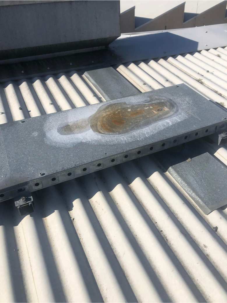
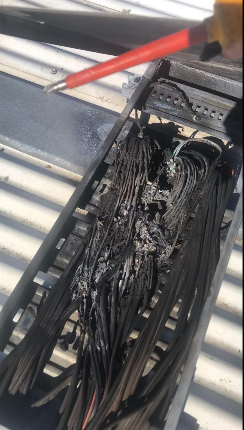
It should be noted that earth faults are ALWAYS a problem. Earth faults are often ignored because they may be intermittent and the system may be performing as expected and visual inspection may not reveal any issues. However, even if the earth fault is small, this earth leakage could damage components over time, the fault could propagate into a larger issue and in worst case scenarios, create live exposed metallic parts or create fires. The image below (left) shows corrosion due to an earth fault. The earth fault caused an arc which damaged the wire tray, and burnt many of the wires (right) severely decreasing site production. To avoid this, earth faults should ALWAYS be investigated.
How are solar inverters protected from an earth fault
Most solar inverters will have an earth fault detection and interruption (EFDI) device (in accordance with AS/NZS4777.2 clause 2.4) to detect and stop earth faults. It can identify the earth fault, generate an error code, and shut down the inverter. Where EFDI is internal to the inverter, inverters will detect and interrupt the earth fault at insulation resistance measurements in accordance with Table 2.1 from AS/NZS4777.2.
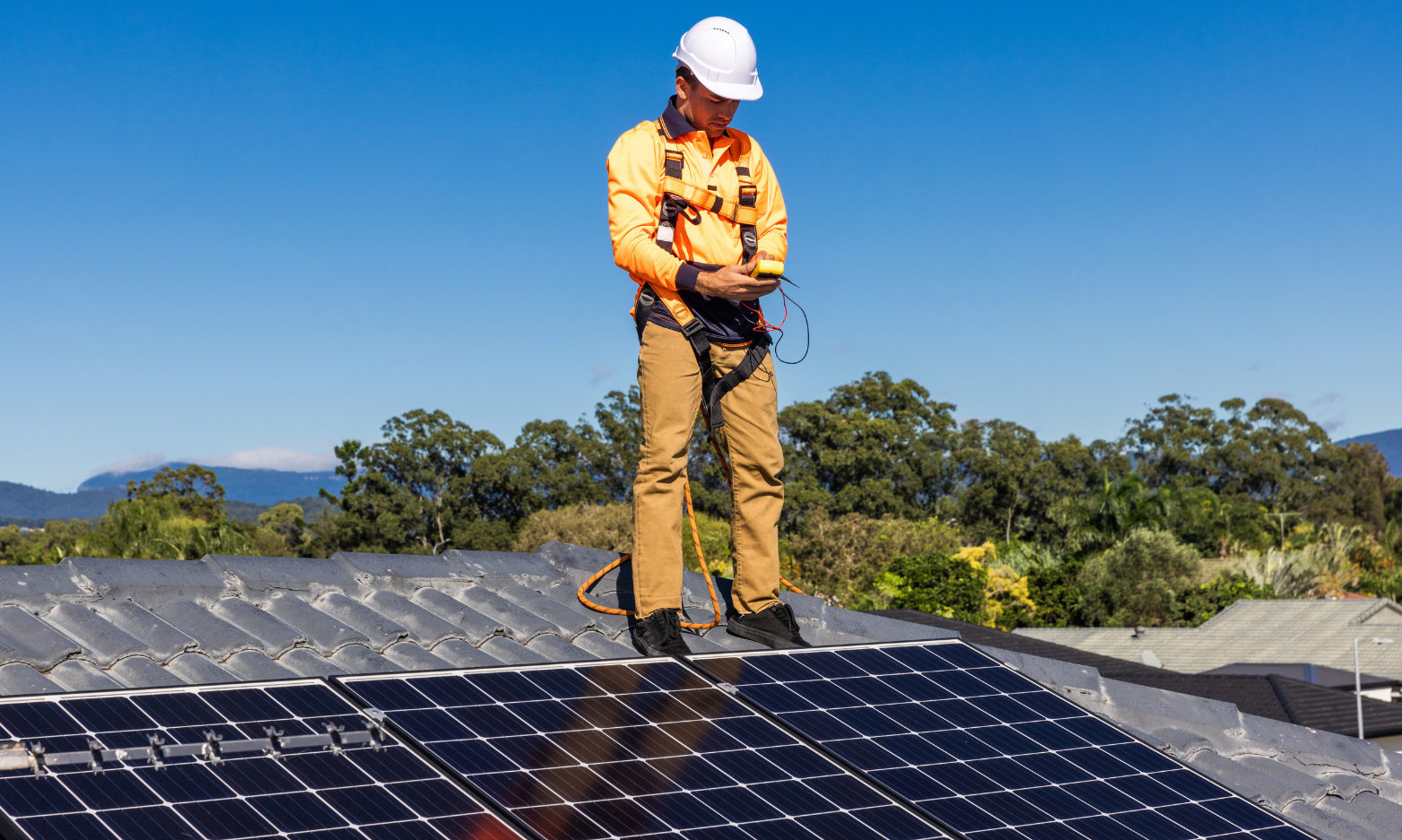
Working on a PV system always requires PPE
Any time you work on an energized system, it’s essential that you use appropriate personal protective equipment (PPE). Though the incident energy of a solar PV fault tends to be relatively low (given that PV is current limited), if there is an arc, it tends to be sustained and the working distance may be small. AS/NZS 5139 Appendix F provides information on PPE and arc flash calculations for BESS, however these calculations can also be used for PV. The following table summarises the PPE required for the arc flash categories.
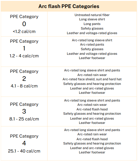
Smaller residential PV systems may only require electrically insulated gloves. Larger commercial systems, however, may require flame-resistant clothing, electrically insulated gloves, and an arc flash face shield. Some installations may require a complete arc flash suit to protect against potential hazards. Understand your company’s rules and the hazards of the equipment you’ll be working on so you can protect yourself with the appropriate PPE.
How to test energized DC PV string circuits with earth faults
Once the insulation resistance is confirmed to be below the required value as per AS/NZS 4777.2 and the affected string or strings are identified, further testing can begin. The specific location of the earth fault can be identified by measuring the voltage of the affected string or strings. Module open circuit voltage (Voc) can be found on the module label or data sheet and the PV string voltage is calculated by multiplying the module Voc by the number of modules in series. Remember that voltage is affected by temperature so consider the cell temperature of the module and adjust your simple calculation accordingly.
Test for current on each string first
It’s critical that you test for current on both the positive and negative conductors before opening any fuse holders. Double earth faults or installation errors can lead to closed circuits where short circuit current (Isc) may be present. Opening a fuse holder, disconnection point or ELV connector (eg MC4) while current is flowing is dangerous. It can create a DC arc that can harm both you and the equipment.
Use a current clamp to verify zero current in each PV circuit string before opening the circuit.
De-energize and lockout/tagout (LOTO) where you’re working
Isolate the equipment to be tested. Open (turn off) the load break rated disconnect in the section where you’re working — this may be a specific area or every isolator or disconnection point in the array.
Once the strings are open circuited, apply lockout/tagout devices to each component to prevent the system from being re-energized accidentally. Label each LOTO device with the worker’s name, phone number, date, and the work being performed.
Inspect the PV array visually
Before conducting any tests, it’s a good practice to visually inspect the array. You can find many earth faults by looking for obvious signs of damage, like burn marks on modules or melted connectors.
How to locate an earth fault in a PV string circuit by the numbers
A PV string circuit without an earth fault will have open circuit voltage (Voc) between positive and negative conductors. It will have zero volts from positive to ground and from negative to ground.
When an earth fault is present, measurement will show Voc between positive and negative conductors, but it may also reveal a value other than zero on the positive to ground, negative to ground, or both.
A severe fault may include line to line faults as well as earth faults where location identification may be easier to achieve visually. However, if the earth fault is localised then the earth fault can be located using the proportion of voltage from array positive or negative to earth over the open circuit voltage compared to the number of panels in the string. Let’s look at an example:
Voltage to Ground on Both Positive and Negative Sides
In this example, a string of 16 modules with a Voc of 50.62 VDC per module should expect a total open circuit voltage on the string of around 809.92V
- Measure between positive and negative conductors:
- Reading: 809.92 VDC
- Measure positive-to-ground:
- Reading: 607.44 VDC
- Measure negative-to-ground:
- Reading: 202.48 VDC
- These readings indicate voltage to ground on both sides. We can determine the fault location by dividing the voltages by the string Voc (eg 202.48V/809.92V is 25% of the way up the string)
- Result: The fault is located at or after module 4 and before module 5 from the negative.
Voltage to Ground on the Negative Side Only
- Measure between positive and negative conductors:
- Reading: 809.92 VDC (as expected).
- Measure positive-to-ground:
- Reading: 0 VDC (normal behaviour).
- Measure negative-to-ground:
- Reading: 809.92VDC.
- Divide the voltage readings by the module Voc:
- Result: The fault is located in the positive sub-array conductor (the entire string is on one side of the fault).
In cases like this, the ground fault occurs in the wiring, which can often be missed if only one voltage-to-ground measurement is considered. The first place to inspect would be your terminations and if you don’t notice anything there, perform a visual inspection over the entire length of the conductor.
Identifying Intermittent Earth Faults
Some earth faults only appear in wet conditions, either with morning dew, rain or even condensation in combiner boxes or within PV modules. Unfortunately, these types of faults can only be located when those conditions are present. In order to recreate these conditions, it may be necessary to spray the system down with a hose and conduct the tests as described above.
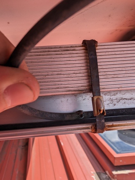
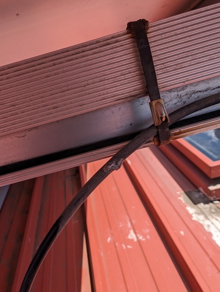
If this is required to be done however, it is critical that extra safety precautions must be taken since you have now created a dangerous situation for working with electrical equipment in a wet environment and working on a wet slippery roof. These safety precautions must be identified clearly in your Safe Work Method Statements (SWMS) and adhered to during the works. The photos below show an intermittent earth fault caused by a small nick in a panel cable.
How to repair earth faults in PV systems
Once you’ve found the earth fault, the next step is to repair it by replacing the affected conductor or module.
If the damaged conductor is in conduit or free air, you can replace it with a new, undamaged conductor. A single conductor in a conduit with other conductors may be challenging to replace without removing all conductors from the conduit.
If the conductor is a lead to a PV module, you might try to bypass the affected module until a replacement module can be found. Alternatively, you may replace the lead yourself however you must verify that this does not affect the workmanship or performance warranty of the module..
If the earth fault is within the PV module itself you should reach out to the manufacturer and request a warranty replacement. You will most likely need to provide photographic evidence and possibly your tests to prove the module is causing the earth fault.