AS/NZS 5033:2014 Amendment 2 changes to sizing DC isolators came into effect on 28th June 2019. The new requirements simplify the process of selecting an isolator and ensure that thermal effects are taken into account. It addresses fire risk issues and improves design and installation practices. This is an essential part of Grid Connected Solar Design
What are DC Isolators?
A load-breaking disconnection device, typically referred to as an “isolator” in the Australian solar industry, is required on most PV arrays (some arrays with AC modules or microinverters are excepted) according to AS/NZS 5033:2014. They have the capacity of making, breaking and carrying currents in normal circuit conditions and in specific overload conditions.
Two main types of disconnector meet this requirement from 28th June 2019: switch-disconnectors and circuit breakers. Circuit breakers have the additional ability to automatically interrupt overload currents, while switch-disconnectors do not. Both can be referred to as isolators in signage for simplicity, but each have different sizing and installation requirements specified in AS/NZS 5033:2014.
Amendment 2 contains significant changes for sizing and installing switch-disconnectors, but not for circuit breakers. In this article, the term ‘isolator’ typically refers specifically to switch-disconnectors used for load-breaking disconnection in PV arrays (Figure 1).
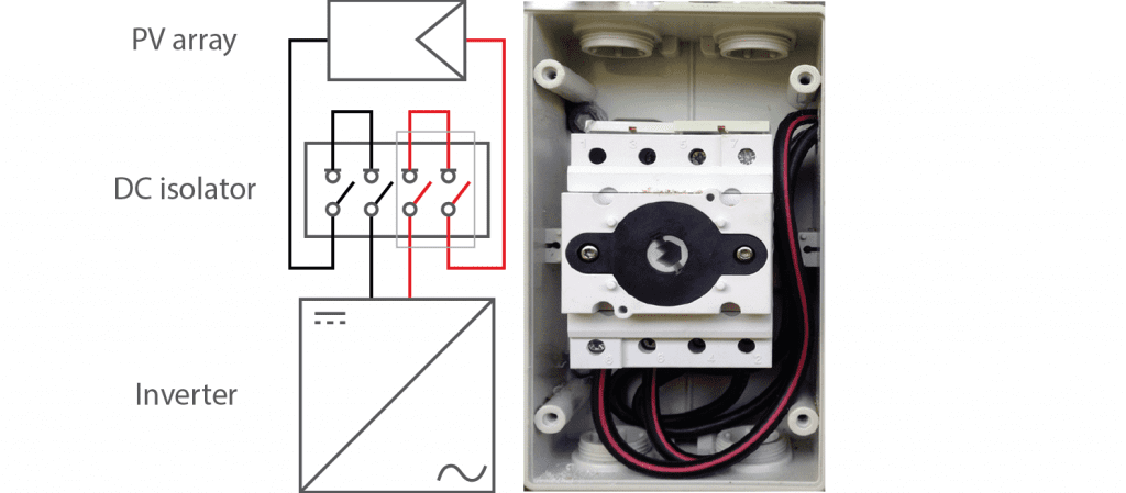
Figure 1: Isolator schematic
Changes in Amendment 2 for DC Isolator Sizing
Amendment 2 introduced new installation and product requirements for switch-disconnectors to improve the uniformity of product datasheets and ensure the isolators can withstand the harsh Australian climate.
The main changes are:
- Switch-disconnectors must now be compliant to AS 60947.3:2018, a modified version of international standard IEC 60947.3 with requirements specific to Australia.
- Minimum ingress protection (IP) rating of IP56NW is required for outdoor isolators in individual enclosures.
- Isolators must be sized to the rating corresponding to the utilization category DC-PV2.
- Standardising and simplifying the temperature effects and corresponding isolator rating. Local temperature records are not to be used, instead the standard defines ambient temperatures for use:
- Expected indoors and outdoors fully shaded ambient temperature 40°C.
- Expected outdoors exposed to sunlight ambient temperature 60°C.
The manufacturer must provide corresponding current ratings for each scenario.
- Manufacturers must provide the following data for an isolator:
- Ie rated operational current for the PV array maximum voltage Ue.
- I(make) and Ic(break) rated currents under fault conditions for the PV array maximum voltage Ue, if a non-separated inverter is used.
- Introduction of a new method to size the isolator.
- Additional exception for inverter-integrated isolators: Isolators integrated to the enclosure of the isolator can be used if requirements outlined in Clause 4.3.5.1 are met. The inverter manufacturer can provide advice concerning this.
Determining DC Isolator Rating
To start sizing DC isolators required for a PV array, you need to find out:
- Type of inverter to be installed (separated or non-separated/transformerless).
- PV array open circuit voltage corrected for lowest expected temperature (i.e. PV Array Maximum Voltage).
- PV array short circuit current multiplied by 1.25 as stated in the standards.
- Installation location of the isolator (indoors, outdoors, or outdoors but fully shaded).
Apply the three steps below. The isolator must meet all requirements to be used with the chosen array configuration.
The DC isolator sizing process can be different for inverter-integrated isolators, so refer to the inverter manufacturer or their installation manual if intending to use the in-built isolator.
Step 1 – Thermal effects
Check that 1.25 × ISC_ARRAY is less than or equal to Ithe for the installation conditions:
- Indoors at 40°C ambient for isolators installed indoors.
- Outdoors at 40°C ambient for isolators installed outdoors in a location fully shaded all day (e.g. carport, verandah).
- Outdoors at 60°C ambient with solar effects for rooftop isolators or isolators installed externally where the enclosure or shroud will receive direct sunlight.
This ensures the isolator can interrupt maximum current even during high temperatures.
Step 2 – Operational conditions.
Consider the isolator configuration when the positive and negative conductors are operating in series (Figure 2). Looking at the first row where Ue is higher than the PV Array Maximum Voltage, check that Ie is higher than 1.25 × ISC_ARRAY. This ensures the isolator can interrupt maximum current under normal operating conditions.
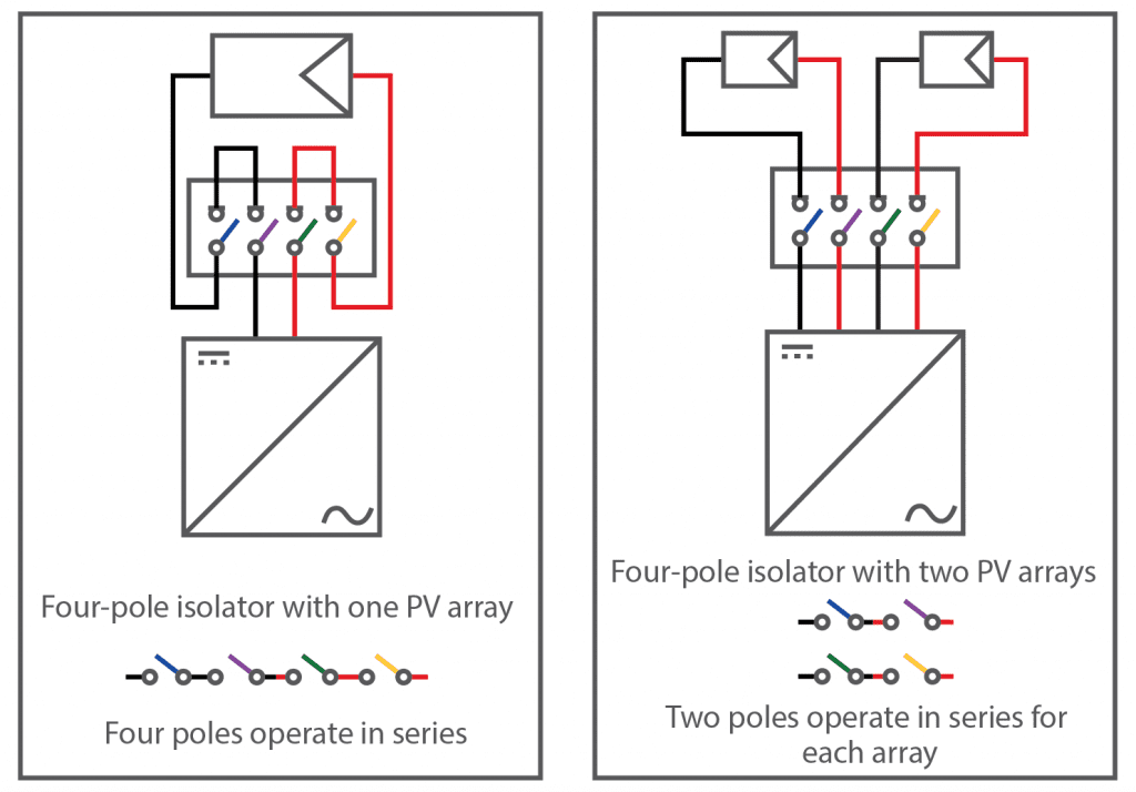
Figure 2: Isolator operation under normal conditions: Ie
Step 3 – Fault conditions
For non-separated (transformerless) inverters only. Consider the isolator configuration when the positive and negative conductors are not operating in series (Figure 3). Looking at the first row where Ue is higher than the PV Array Maximum Voltage, check that I(make) and Ic(break) are higher than 1.25 × ISC_ARRAY. This ensures the isolator can interrupt maximum current under earth fault conditions. However, doing this may degrade the isolator, so it should be replaced after it is used to isolate the system under fault conditions.
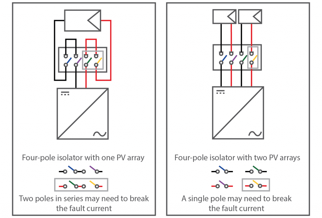
Figure 3: Isolator operation during an earth fault: I(make) and Ic(break)
Sizing DC Isolator Example
The switch-disconnector with specifications given in Table 1 will be used as the rooftop PV array isolator for an array with a transformerless inverter. The system has a PV array maximum voltage of 840 V and an array short circuit current of 17 A. The following example checks whether the isolator selected is suitable for this purpose.
Table 1: Isolator datasheet
| Identification | Rating Data | ||
| Ith rated thermal current, unenclosed, at 40°C shade ambient air temperature | 32 A | ||
| Ithe rated thermal current, indoors, at 40°C shade ambient air temperature, in a specific dedicated enclosure | 32 A | ||
| Ithe rated thermal current outdoors at 40°C shade ambient air temperature without solar effects in a specific dedicated enclosure rated IP 56NW | 32 A | ||
| Ithe solar current value, outdoors at 60°C shade ambient air temperature, with solar effects in a specific dedicated enclosure rated IP 56NW | 28 A | ||
|
| Ue | Ie | I(make) and Ic(break) |
| 2 pole  | ≤500 | 32 | 128 |
| 600 | 32 | 128 | |
| 800 | 27 | 108 | |
| 1000 | 13 | 52 | |
| 4 pole  | ≤500 | 32 | 128 |
| 600 | 32 | 128 | |
| 800 | 32 | 128 | |
| 1000 | 32 | 128 | |
Step 1. 1.25 × ISC_ARRAY = 1.25 × 17 A = 21.25 A. This isolator will be installed outdoors in direct sunlight. Ithe under these conditions is 28 A according to Table 1, which is higher than 21.25 A, so the rating is acceptable.
Step 2. The isolator has four poles and there is only one string to be switched, so the positive and negative conductors will each go through 2 poles. During normal operation, these operate in series, so there are 4 poles total operating in series. Looking at the 4 pole configuration, the next highest Ue above 840 V is 1000 V, and the corresponding Ie is 32 A. This is higher than 21.25 A, so the rating is acceptable.
Step 3. The positive and negative conductors each go through 2 poles. This is a transformerless inverter, so under earth fault conditions, either conductor may switch the full array current and voltage. Therefore, looking at the 2 poles in series configuration, at the 1000 V row, the I(make) and Ic(break) for the chosen configuration is 52 A. This is higher than 21.25 A, so is acceptable.
The DC isolator meets all three sizing requirements from AS/NZS 5033:2014 Amendment 2. Therefore, this isolator and the PV array configuration are compatible.
Conclusion
Properly sizing DC isolators are a crucial part of a PV design. The changes to AS/NZS 5033:2014 and AS 60947.3 address temperature safety issues and fault conditions by simplifying sizing calculations. Manufacturers have the responsibility for ensuring that their isolators can be used in specified operating conditions, but system designers and installers must ensure they can correctly apply the new rules to remain compliant.