The signage requirements of AS/NZS 4777.1:2024 build on those of the 2016 standard, introducing new elements such as EV labels and IPSD labels that were not previously included. While key requirements for shutdown procedures, multiple supply warnings, and accurate labelling of circuit breakers (CBs) and isolators remain largely unchanged, the 2024 update introduces important new obligations that installers must be aware of. This article will explore these updated requirements, ensuring that you remain compliant before the standard becomes mandatory in February 2025.
General Notes for all Signs:
For any outdoor signs installed, an unchanged rule is that the sign must be engraved or etched to permanently display the sign clearly through any potential environmental wear. A lot of issues were seen where markers were used to write down information on signs, and they were found to be faded a year later. Please make sure there is a guarantee that the text is durable and indelible for the lifetime of the IES. This also includes ensuring the stickers are stuck on flat surfaces that don’t cause any risk of signs peeling off.
Examples of signs that are installed inadequately and are found to be peeled off
Circuit Breaker Labels:
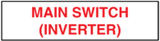
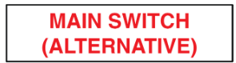
All main switch labels should be visibly distinct from standard labels such as isolators. It is recommended that main switch labels have red text to meet this requirement. AS/NS 3000:2018 2.3.3.5
- A sticker to be placed on top of the CB of the Inverter Main Switch in the switchboard. If the inverter has two supplies: a Main Supply (supplementary) and Backup Supply (alternative), please add the supply type to the sign. Ex: Main Switch (Supplementary ). If the installation has two different inverters, a PV Inverter and a Battery Inverter, number the inverters or describe the inverter to accurately differentiate them. Ex: Main Switch (Inverter 1 Supply) or Main Switch (Inverter Sungrow Supply). AS/NS 4777.1-2024 6.3 (a)
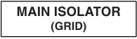
- “Main Switch (Grid)” sticker is to be placed above the grid supply main CB in the switchboard that contains solar. The word “Grid” can be interchangeable with “Mains” and “Normal”. AS/NS 4777.1-2024 6.3 (b)

- When a distribution board has a main switch/isolator for the entire board from the grid, and that distribution board has a direct connection to the inverter, please put the “Main Isolator (Grid)” sign on that distribution board main switch. AS/NS 4777.1-2024 6.3 (c )
- The sticker “Main Switch (Alternative)” is to be placed on the main CBs of the alternative supplies of the system. Please refer to AS/NZS 3000 for the full definition of an alternative supply, but it is essentially an energy source that can be an alternative to grid power (eg. Batteries or bidirectional EVs). If there is a situation where the same main switch is for both the supplementary and alternative supply, please use the alternative supply sign. AS/NS 4777.1-2024 6.3 (d)
- The sticker “Main Switch (Independent)” should be attached to CB switches of the independent supply from the IES. AS/NS 4777.1-2024 6.3 (e)

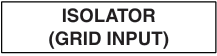
- The sticker “Isolator (Grid Input)” should be placed on the individual overcurrent protection CB connected to the AC input of the inverter coming from the grid. AS/NS 4777.1-2024 6.3 (f)
Switchboards or Distribution Boards:
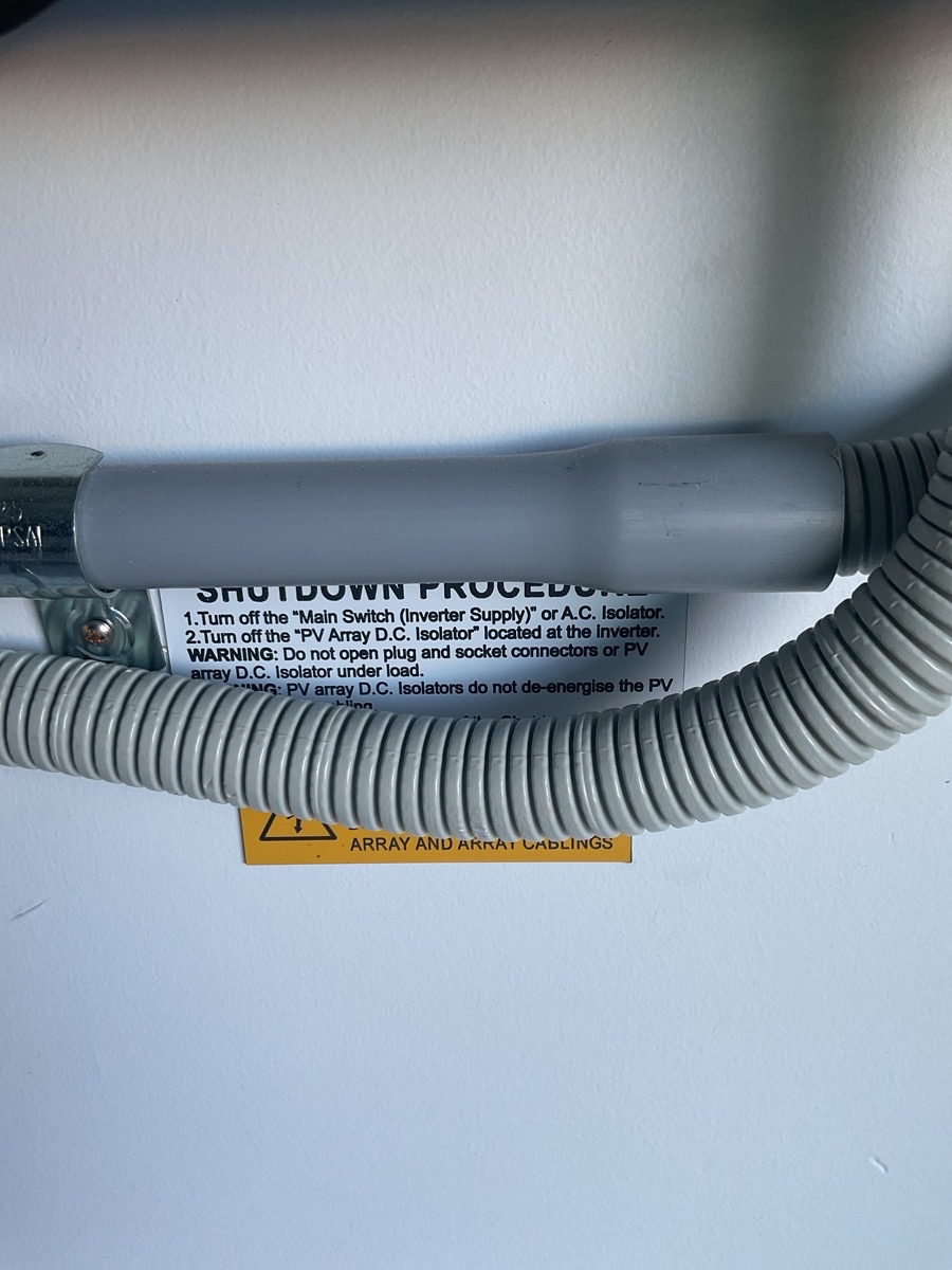
- Shutdown Procedure signs are expected to be visibly present at the switchboard or distribution board connected to the solar system. Please keep in mind that the switches mentioned in the Shutdown Procedure MUST match those installed on site. There are many occurrences where installers just slap on any shutdown procedure that mention switches that don’t actually exist in the system. Shutdown procedures should dictate the procedures for the PV Array, Inverter, and the Battery if they exist in the system. AS/NS 4777.1-2024 6.2

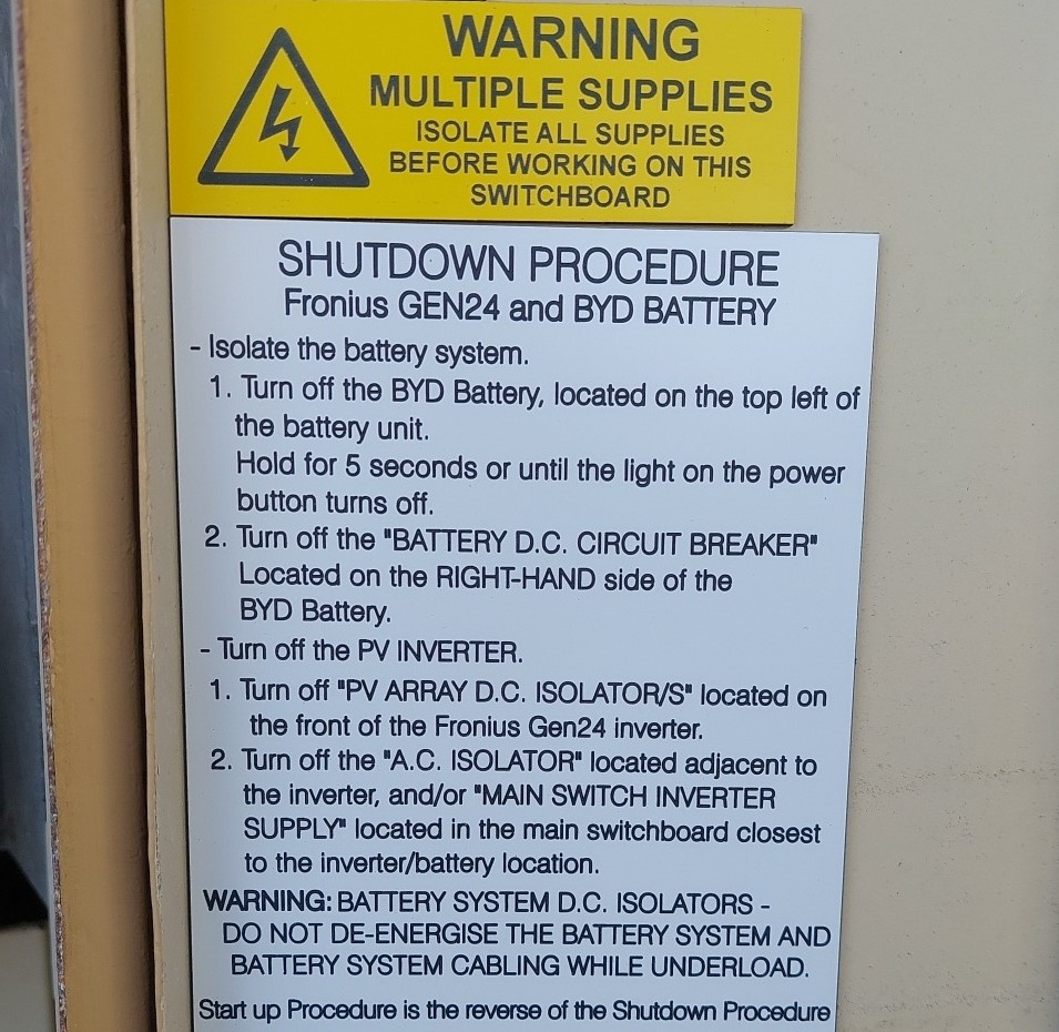
Here is an example of a compliant shutdown procedure that is visibly installed in the MSB and has an elaborate and detailed description
Here is an example of a non-compliant shutdown procedure that was not visibly installed
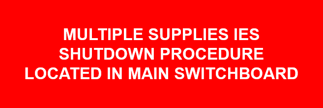
- If a building has a fire panel, then the Shutdown Procedure locating sign in red should be placed on any fire panel with instructions to find the IES Shutdown Procedure efficiently in an emergency. AS/NS 4777.1-2024 6.2
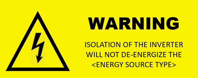
- When shutting down the IES will not de-energize the energy source, this sign is needed to indicate that more steps are needed to be taken to de-energize the system safely. AS/NS 4777.1-2024 6.2
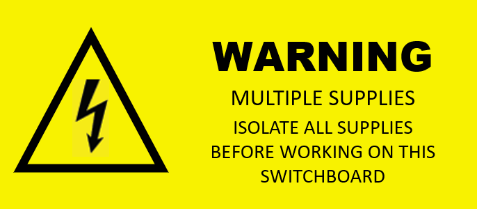
- On the main switch board or distribution board connected directly to the IES, please place the ‘WARNING MULTIPLE SUPPLIES ISOLATE ALL SUPPLIES BEFORE WORKING ON THIS SWITCHBOARD’ sign. AS/NS 4777.1-2024 6.3 (g)
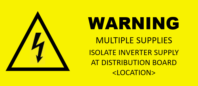
- If the IES is connected directly to a distribution board, a sign that says ‘WARNING MULTIPLE SUPPLIES ISOLATE INVERTER SUPPLY AT DISTRIBUTION SWITCHBOARD [Location]’ on the main switch board or other distribution boards connected to the distribution board of the IES system. It should also indicate the location of the distribution board in direct connection to the IES. This is done to safely isolate the IES supplies from the circuitry and mitigate risk of safety hazards. AS/NS 4777.1-2024 6.4
- Please place a site plan or labelling signs that accurately locate the Battery, Inverter, and other energy supply devices when the devices are not clearly visible from the switchboard. Alternatively, site plans from other standards and for other purposes could also integrate the battery, inverter, and other device locations. AS/NS 4777.1-2024 6.5
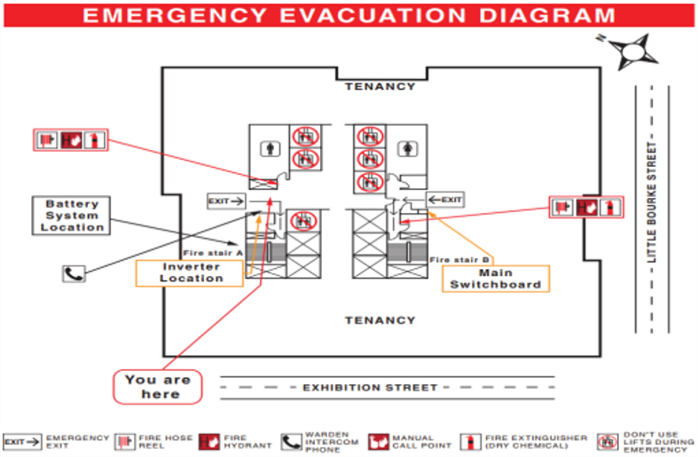
Example of an Emergency Evacuation Diagram indicating Inverter and MSB Locations
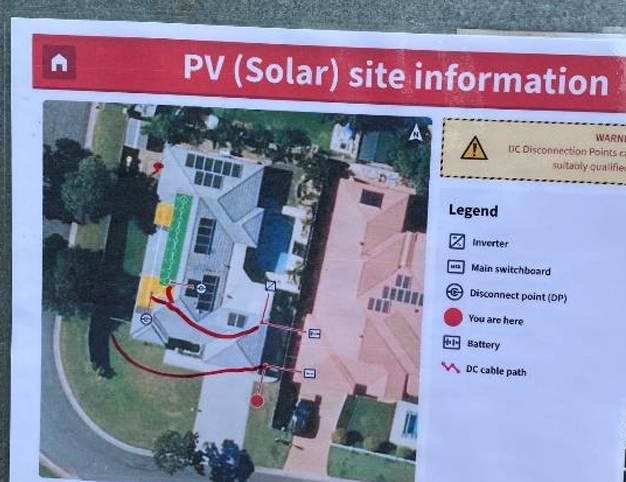
Example of a Solar Site Plan indicating Battery and Inverter Locations
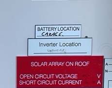
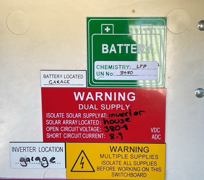
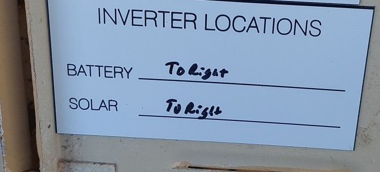
Examples of individual labels locating the Battery and Inverter Locations
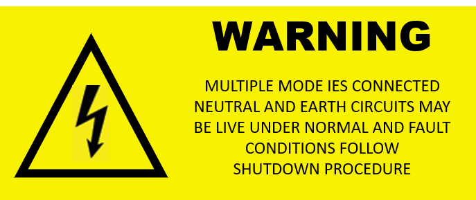
- All switchboards and distribution boards electrically connected to a multi-mode IES should have the Multiple Mode IES warning sign attached to it to let the person know that there is a specific shutdown procedure to safely shutdown and isolate the system. AS/NS 4777.1-2024 6.8
- A warning sign saying phrases such as “Limited Power Output” and “Only Available When Grid Power Is Interrupted” sign is to be installed at the outlet of the sockets of the substitute supply of the multimode inverter if it has a substitute supply function. A current example of when to use this sticker is for the use of PV Points in Fronius’ Primo & Symo GEN24 Inverters, but note that the PV Point is not technically considered a Substitute Supply because it is not electrically separated.AS/NS 4777.1-2024 6.9
- For portable IES systems (AS/NZS 4777.1-2024 5.7.1) that typically provide an alternative supply of power, the purpose of their inlet plugs should be clearly labelled on the plug. This includes EV’s that act as a Portable IES. The sign should have phrases that include “Isolated Output Inverter Only” and “RCD Protected and Equipotential Bonded Inverters Shall not be Connected”. AS/NS 4777.1-2024 6.10
- When there are multiple energy sources connected to an inverter, a warning sign must be placed that indicates all supplies must be turned off to achieve complete isolation for the inverter. The sign should be placed on or near the inverter. AS/NS 4777.1-2024 6.11.1
- All AC and DC conduit should be labelled to clearly identify what energy source it is attached to. For example, battery DC conduit should state Battery on it. The labels should be visible and reoccurring every 2m along the conduit or cable duct used. AS/NS 4777.1-2024 6.11.3.2
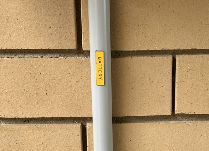
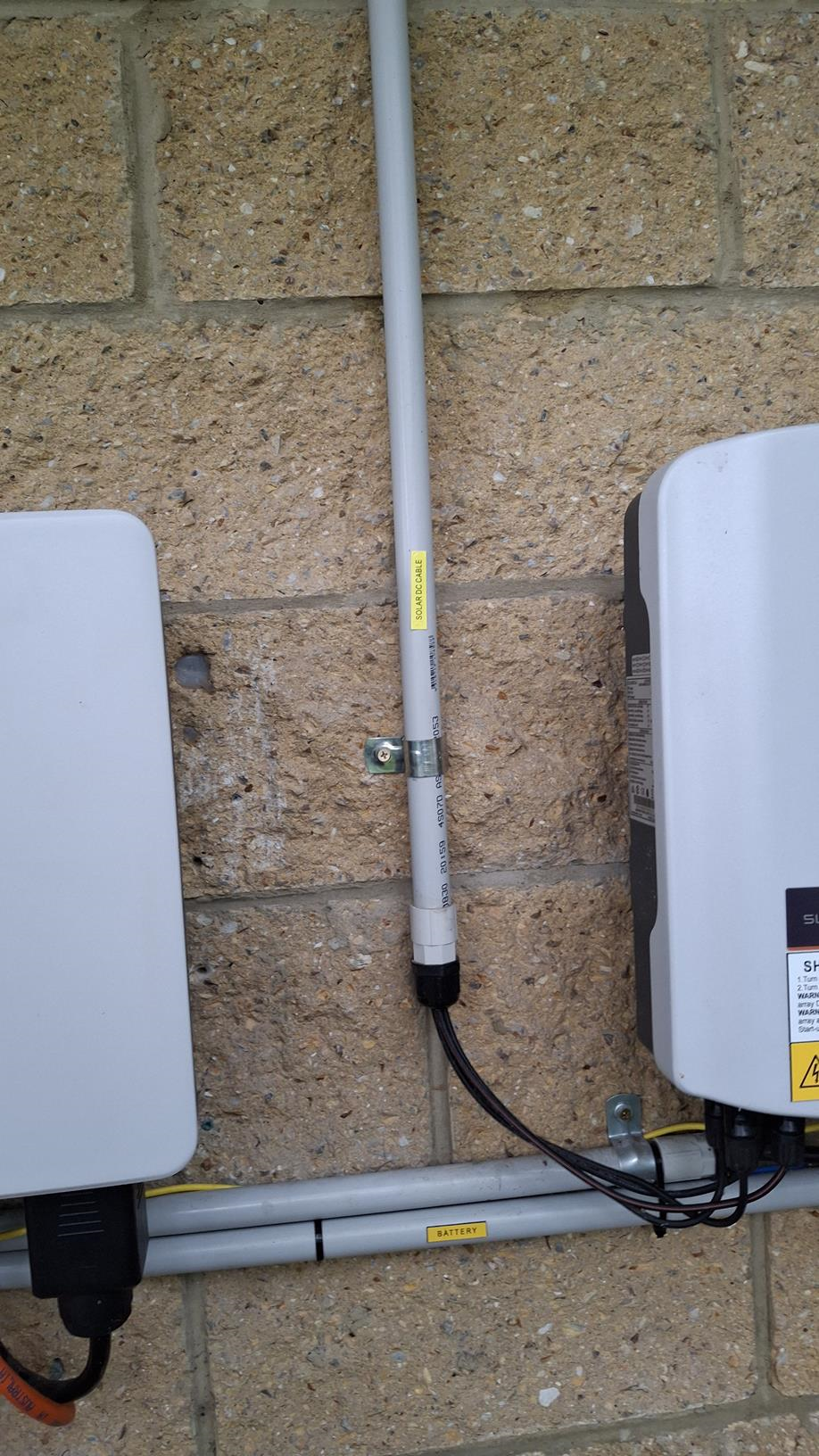
Examples of Battery and Solar labels for DC Conduit
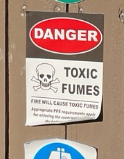
- When a site has a potential hazard that has been identified with an energy source other than an electrical hazard (eg. Chemical or toxic fume), a sign indicating the installation and the potential hazard must be placed. AS/NS 4777.1-2024 6.11.3.3
Isolators:
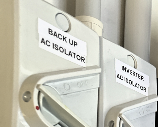
- AC isolators connected to the outputs of inverters should be labelled as “Inverter AC Isolator” and any number or description that accurately represents the device and is correctly matched in the Shutdown Procedures related to it. For example, if the inverter has two AC isolators, one for the Main Supply and another for the Backup Supply, then the isolators will be labelled “Inverter AC Isolator” and “Inverter Backup AC Isolator”. If there are multiple inverters with multiple AC isolators, numbers can be designated to them, such as “Inverter #1 AC Isolator” “Inverter #2 AC Isolator” and “Inverter #3 AC Isolator” AS/NS 4777.1-2024 6.6 & 6.7.

An example of individual AC Isolator labels with differentiating descriptions
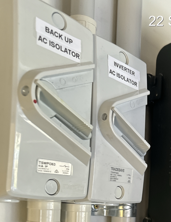
An example of labelled isolators with different descriptions
Electric Vehicle with Reverse Power Transfer
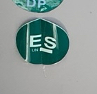
- Just like any other energy source, a green circular reflective sign of at least 100mm in diameter must have “EV” written on it on/near the MSB or meter box. It must also be clearly visible for any emergency personal to identify. AS/NS 4777.1-2024 6.11.2

Energy Sources with No Standards:
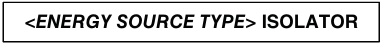
- When installing an isolator for an energy source that doesn’t have a standard, please label the isolator associated with it as “<Energy Source, Type> Isolator”. Don’t forget to change the type of power, either AC or DC. For example: Wind Turbine AC Isolator. The same rules exist for these isolators, where multiple isolators for the same energy source should be numbered or names to easily identify for the shutdown procedure and safe isolation. For example: “Wind Turbine 1 AC Isolator” & Wind Turbine 2 AC Isolator AS/NS 4777.1-2024 6.11.3.1(c ).
- Clear isolation instructions should be labelled when needed. For example: “ISOLATE AT MAIN SWITCHBORD BEFORE OPERATING THIS ISOLATOR” 4777.1-2024 6.11.3.1(a)
IPSD Additional Signs
- Wherever an IPSD is used, a SLD drawing should be printed at the MSB, with a size of at least A3, to identify how the IPSD is connected to the different electrical installations it is supplying power to. 4777.1-2024 6.12.1
- When the IPSD current sensors are installed and hidden behind a switchboard panel, a sign saying “Warning: Do Not Remove IPSD Sensing Devices” should be clearly placed on the switchboard panel. 4777.1-2024 6.12.2