Cable sizing and derating are critical elements in any electrical project, not just solar power installations. Most electricians rely on Australian/New Zealand Standards AS/NZS 3008.1.1 and AS/NZS 3000 to provide the answers necessary to adequately size and derate cables for a given load in any situation. In some scenarios, a specific site or installation may present conditions that are different to those upon which AS/NZS 3008.1.1 was developed, and other specifications or calculation methods that allow greater flexibility may become necessary to select an adequate cable. In this article, we will compare the AS/NZS 3008.1.1 and IEC 60287 cable sizing and derating methods to solve the thermal current carrying capacity limits of selected cables. In doing so, we will illustrate the cases in which AS/NZS 3008.1.1 was designed to be used, where more detailed engineering solutions provide tailored inputs for site specific conditions, and provide a comparison between the two.
What is Current Carrying Capacity?
In any electrical installation, whether LV or HV, it is crucial that the cables are appropriately sized to carry the operational current of the devices or equipment they power. In addition, the cables need to do so without significant resistive losses, and also be protected against overcurrent in the event of a fault.
A cable’s current carrying capacity (or CCC) is deemed suitable when:
IB ≤ IZ, where:
- IB = design current of circuit, i.e. maximum demand for a load or maximum generation for a generator
- IZ = continuous current carrying capacity of the chosen cable, derated according to installation method, grouping with other cables (mutual heating effects) and environmental conditions
- It is also important to note that IZ shall also be greater than the trip rating of any protection devices, such as a fuse or circuit breaker, used on that circuit, in accordance with AS/NZS 3000 or AS/NZS 5033 as appropriate. This is especially crucial in PV DC circuits where fusing is installed.
In Australia and New Zealand, AS/NZS 3008.1.1 – Cables for alternating voltages up to and including 0.6/1 kV is the primary resource for calculating the value of Iz, providing tabulated CCC and derating values for the most common installation scenarios in these regions, making it an incredibly useful resource for a wide range of applications. Section 1.3 of AS/NZS 3008.1.1 names alternative specifications that are permitted to be used for calculation of Iz under the installation methods/scenarios that are not covered by AS/NZS 3008.1.1, one of which is by calculation according to IEC 60287. For a detailed explanation of the AS/NZS 3008.1.1 cable selection process for DC circuits, take a look at our previous technical article:
Solar PV and Cable Selection
As PV systems continue to decrease in cost and the development of large, uniform commercial rooftops and ground-mount systems become increasingly common, there is a decreased reliance on individual string or MPPT circuits and a shift towards central (or so-called “distributed central”) inverters, which allow for fewer, larger sub-array cables to be run between the array and the inverter/s. As the sub-array cables are typically sized much more closely to their design currents than string cables, it is essential that deratings be correctly applied to the sub-array cables.
The installation and application conditions for a typical photovoltaic generator’s DC circuits are notably different to the conditions offered in AS/NZS 3008.1.1. The use of this standard can produce conservative values of IZ, resulting in cables being sized larger than may be necessary. At the same time, while the tabulated deratings presented in AS/NZS 3008.1.1 are useful for simple trenches, more complex trenches can introduce additional deratings that further reduce the CCC beyond the deratings in AS/NZS 3008.1.1. This article will explore some of the key differences between the results produced by AS/NZS 3008.1.1 and IEC 60287 when determining the CCC of underground circuits, considering:
- Simple comparison:
- DC rather than AC voltage and current
- Daily load profile
- Tiered trench designs.
- Minimum clearance between trenches to avoid mutual derating.
- Thermal derating for cables where IB < 35% of IZ.
The IEC 60287 calculations will be performed using the Cableizer software package, which uses computational analysis based on IEC standards to calculate thermal cable ratings, i.e. the maximum steady-state current that can be carried by a circuit without exceeding its maximum permissible operating temperature. The software offers a range of different calculation methods published in the international standards (IEC) and other technical specifications. Models can be built with comprehensive specification of electrical, mechanical, thermal and environmental input parameters for site-specific simulations.
AS/NZS 3008.1.1 and IEC 60287: Comparisons
1. Comparison for cables in underground wiring enclosures
Case 1.1 – AC Circuits
In the base case, we will compare the maximum continuous current calculated according to IEC 60287 with the tabulated result from AS/NZS 3008.1.1. The modelled circuit is:
- 400V (ph-ph) AC.
- 2x1C/ph 400mm² Cu X-90 cables (one circuit per conduit). Note that the neutral is omitted in this model as it is assumed that the three phases are balanced, i.e. there is no neutral current and therefore no heat contribution from the neutral conductor.
- 2x150mm conduits buried with 500mm coverage, touching in one row.
- Ambient soil temperature of 25°C, thermal resistivity of 1.2mK/W.
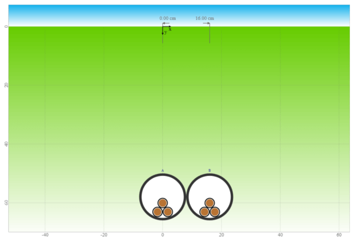
Figure 1: Case 1.1 – 400V AC circuit with two circuits in individual conduits
| Case | CCC per circuit (AS/NZS 3008.1.1) | CCC per circuit (IEC 60287) | % Difference |
| 1.1 – AC Circuit | 498.0 A | 498.3 A | 0.060% |
The results from the two methods support each other with a negligible margin of difference.
Case 1.2 – DC Circuits (Constant Load)
Next, we keep all elements of the design consistent, but change the circuit voltage to 1000V (+ve to -ve) DC, with two current-carrying cables per circuit.
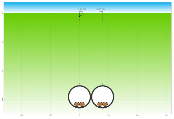
Figure 2: Case 1.2 – 1000V DC circuit with two cables in individual conduits
Using AS/NZS 3008.1.1, we refer to the tables for two single-core cables, rather than three single-core as in Case 1.1. Note however that as AS/NZS 3008.1.1 applies specifically to AC circuits, the CCC produced by this method is applicable, but still not entirely accurate for solar DC circuits, and we now expect some deviation in the calculated results. Watch this space, however, as future releases of the AS/NZS 3008.1 series may soon include the CCC for DC circuits to account for the difference in operational characteristics compared to AC cables.
| Case | AC CCC per circuit (AS/NZS 3008.1.1) | DC CCC per circuit (IEC 60287) | % Difference |
| 1.2 – DC Circuit (continuous load) | 584.0 A | 619.6 A | 6.10% |
The IEC 60287 calculations permit a higher CCC (for DC circuits) for this configuration. This can be attributed to the phenomena of the skin effect and the proximity effect, which both increase the AC resistance of a conductor but have no effect on DC resistance. You can read more about these and other derating phenomena in our technical article below:
Case 1.3 – DC Circuits (Cylic Load)
The tabulated values in AS/NZS 3008.1.1 are based on the continuous operation of the circuit at the design current (i.e. full load). This is an appropriate assumption when the load profile of a circuit is highly variable or unknown. When considering solar PV circuits, however, the load current follows a highly consistent and predictable daily generation profile throughout the year, wherein the cables are loaded for a significantly lower proportion of time.
Calculations of Daily Loss Factor (IEC 60853)
The Daily Loss Factor (represented by the symbol μ) describes the ratio of the average current of a circuit (can be either consumed or produced) in an hourly interval to the maximum current within a given day, and can be defined with the following formula:

- Ii = average current within the hourly time interval (i) of a given day, in A
- Imax = maximum instantaneous current reached within said day, in A
Provided the hourly interval data for a specific solar generator (this can be simulated from using software such as PVsyst), it is possible to calculate the loss factor for every day in a year and use the 24hr period with the highest value of μ as a representative. The example graph below compares a simulated PV system load profile (μ = 0.28) with a sinusoidal load profile (μ = 0.40) and a continuous load profile (μ = 1). The daily loss factor for a PV system will typically fall between 0.2 and 0.38, depending on the location, type of installation (fixed or tracking) and time of year. The Cableizer software package allows for a minimum loss factor of 0.4, so this value will be used for our analysis.
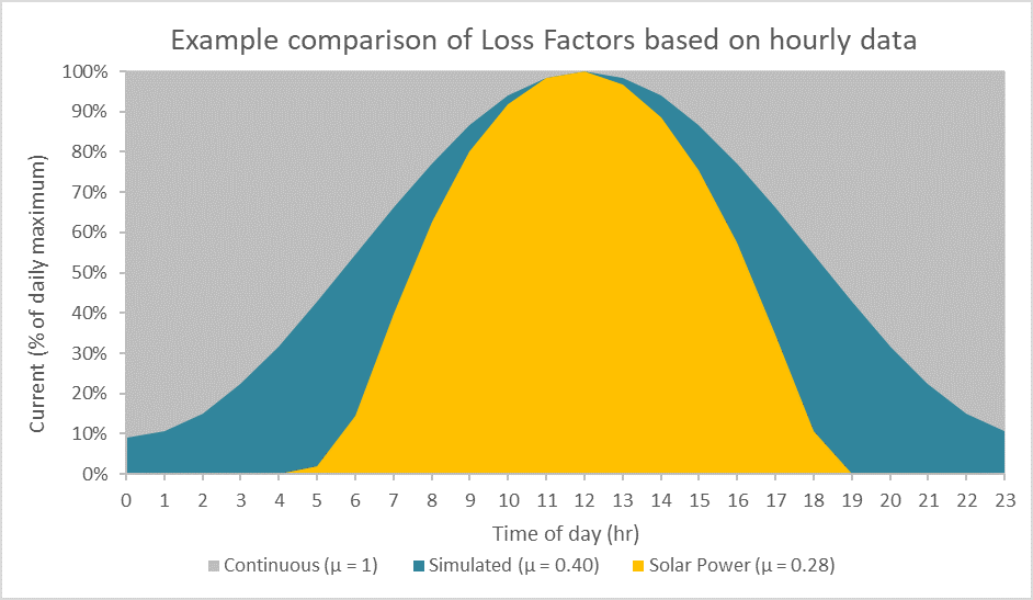
Figure 3: Example of load profiles with varying daily operating capacity, where the load profile of Case 1.3 is represented in blue
| Case | Continuous AC CCC per circuit (AS/NZS 3008.1.1) | Cyclic DC CCC per circuit (IEC 60287 and IEC 60853) | % Difference |
| 1.3 – DC Circuit (Cyclic Load, μ = 0.4)) | 584.0 A | 793.5 A | 35.87% |
When the loss factor of 0.4 is applied we can see that the simulation calculates a further 29% increase in the CCC of the cables, for a total 35% increase over the AS/NZS 3008.1.1 value. This is a result of the PV system circuits being underloaded for a large fraction of the day, enabling the cable environment to cool down periodically and thus allowing a higher current to flow through the circuit than when compared to a continuous load.

2. Tiered trench designs
Like the current carrying capacities, the derating methods presented in AS/NZS 3008.1.1 have been developed to cover the most prevalent trench configurations, but notably do not cover multi-tiered trenches (per Section 1.3 (c) of the standard). Multi-tiered trenches may become desirable in cases where physical constraints (e.g. a small or densely occupied site, or equipment specifications) cannot accommodate an increasingly wide trench of cables in a single row (or “tier”). As soon as conduits are arranged in two or more tiers, these inputs begin to deviate significantly from the inputs in AS/NZS 3008.1.1, thus it becomes necessary to use alternate standards or calculation methods to accurately determine the CCC of the circuit/s.
The following example compares the CCC of a circuit as determined by IEC 60287 with the CCC as determined through inappropriate application of AS/NZS 3008.1.1, to highlight the importance of using the correct inputs. Both methods allow the conductor temperature to reach a maximum of 90°C for X-90 insulation, in accordance with the limits specified in AS/NZS 3008.1.1.
The modelled trench is defined as follows:
- 400V (ph-ph) AC.
- Continuous full load (μ = 1).
- 3x1C/ph 400mm² Cu X-90 cables, then 6x1C/ph 400mm² Cu X-90, using one circuit per conduit in both cases.
- 3x100mm conduits buried at 500mm, then 6x100mm conduits (two tiers) buried at 500mm (same depth of cover in both cases).
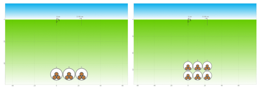
Figure 4: (left) Case 2a – 3 circuits in one tier, Figure 5: (right) Case 2b – 6 circuits in two tiers
| Case | CCC per circuit (AS/NZS 3008.1.1) | CCC per circuit (IEC 60287) | % Decrease |
| 2a – 3 circuits in one tier | 450.0 A | 432.9 A | 3.800% |
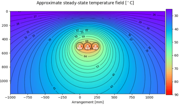
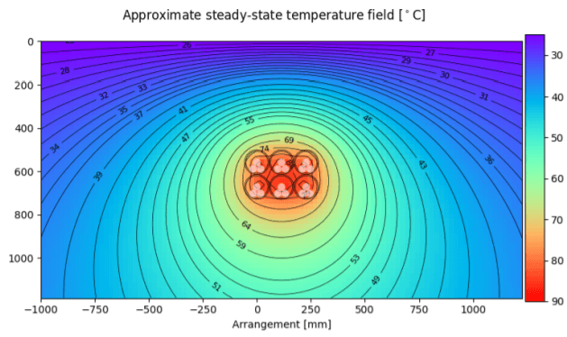
Figure 6: Case 2a – 3 circuits in one tier (thermal heat map simulation)
| 2b – 6 circuits in two tiers | 396.0 A*1 | 336.4 A | 15.05% |

Figure 7: Case 2b – 6 circuits in two tiers (thermal heat map simulation)
*1 AS/NZS 3008.1.1 result for two-tiered trench derived by improperly treating trench as a single row of conduits buried at the depth of the deepest conduit in the two-tiered trench.
The results show that despite a fairly high degree of agreeance for the single tiered trench, AS/NZS 3008.1.1 significantly overstates the CCC of the circuit if inappropriately applied to a two-tiered trench. If designed to carry 396A, the cables in the two-tiered trench would be at risk of overheating, potentially resulting in fire and/or damage to the cables and connected equipment. As AS/NZS 3008.1.1 uses specific assumptions that limit the application of the derating factors for underground cables laid in tier formation, a large variation in results is observed. This is why it is critical to understand how to apply the standard and where alternative standards or calculation methods like IEC 60287 should be used to ensure safe loading of the cables.
3. Minimum clearances between trenches to avoid mutual derating
Certain installations will require that multiple circuits be installed underground in close proximity to each other, sometimes running in parallel for short sections or crossing over each other. This is particularly relevant where large, centralised equipment is involved, for example central inverters with multiple DC combiner box inputs, or main switchboards with multiple incoming and/or outgoing circuits.
Where site constraints and equipment specifications allow, it is generally best practice to avoid or minimise derating between circuits in order to keep component costs down. This can be achieved by spacing trenches out to reduce their mutual thermal derating effects. AS/NZS 3008.1.1 stipulates that the minimum clearance between conduits that will avoid mutual derating is 2m. The following two test cases examine the extent to which this rule can be applied depending on the complexity of a trench design.
Case 3.1 – Simple Trench
In the first case, we will look at a single buried circuit as defined below; first completely isolated and then spaced at 2m clearance from an identical circuit. The CCC of the circuit in both cases will be compared.
- 1000V (+ve to -ve) DC.
- 2x1C 300mm² Al X-90 cables per circuit (one circuit per conduit).
- Loss Factor = 0.5.
- 100mm conduits buried with 500mm coverage.
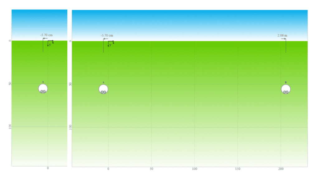
Figure 8: Case 3.1 – 1 circuit in trench (left), 2 circuits with 2m clearance (right)
| Case | CCC – 1x circuit (IEC 60287) | CCC – 2x circuit (IEC 60287) | % Decrease |
| 3.1 – Simple Trench | 532.1 A | 530.0 A | 0.395% |
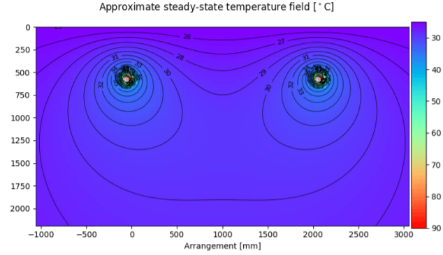
Figure 9: Case 3.1 – 2 circuits with 2m clearance (thermal heat map simulation)
The results show that with two simple trenches composed of a single conduit each, spaced at 2m, the mutual effect on thermal derating between trenches is indeed negligible.
Case 3.2 – Tiered Trench
In the next case, we will repeat the experiment above but with a trench composed of 6 conduits, arranged in two rows of three. Each individual conduit will be defined identically to each conduit in Case 3.1.
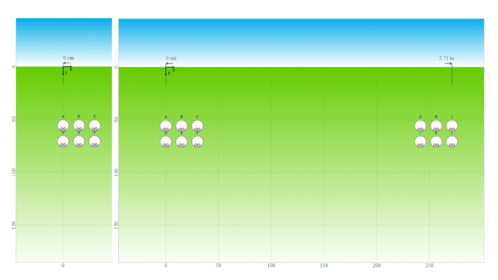
Figure 10: Case 3.2 – 6 circuits in two tiers (left), 12 circuits in two tiers with 2m spacing (right)
| Case | CCC – 6 circuit (IEC 60287) | CCC – 12 circuit (IEC 60287) | % Decrease |
| 3.2 – Tiered Trench | 399.0 A | 391.9 A | 1.779% |
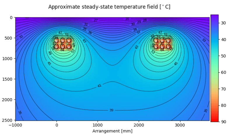
Figure 11: Case 3.2 – 12 circuits in two tiers with 2m spacing (thermal heat map simulation)
Although the impact to the CCC per circuit when the second trench is introduced is relatively small, there is still an increase in derating when compared to Case 3.1. As each trench becomes larger (i.e. more and more conduits get incorporated into each), the 2m clearance between the trenches gets smaller relative to the effective size of the trenches. As this continues, we can expect the CCC to continue decreasing to a non-negligible degree. It is recommended that a project-specific trench design verification be undertaken for all grouped trenches to ensure the effects of mutual thermal derating are within the limits of the components being used.
4. Verification of negligible derating for cables where IB < 35% of IZ
In cases where the design current of a circuit is significantly lower (<35%) than the sustained CCC of the cable, AS/NZS 3008.1.1 does not require that the circuit’s CCC be derated due to grouping or bunching, but still requires derating due to environmental conditions such as ambient temperature (clause 3.5.2.2 (d) of the standard). Often this will be applicable in DC string circuits, where a typical module lead or string cable size of 4-6mm² has a CCC much higher than the typical string current of ~10A. However, remember that Iz is still the current rating of the cable in the relevant type of installation (e.g. in air, enclosed etc.), and that other derating factors such as ambient temperature and depth of bury still need to be considered.
Based on a common test case below, we will use IEC 60287 calculations to assess the maximum temperature reached by underground trenches composed of various quantities of adjacent lightly-loaded circuits. The modelled circuit is:
- 1000V (+ve to -ve) DC.
- 2x1C 6mm² Cu X-90 cables per circuit (two circuits per conduit).
- 10A per cable/circuit, continuous load (μ = 1).
- 50mm conduits buried with 500mm coverage, touching in different configurations.
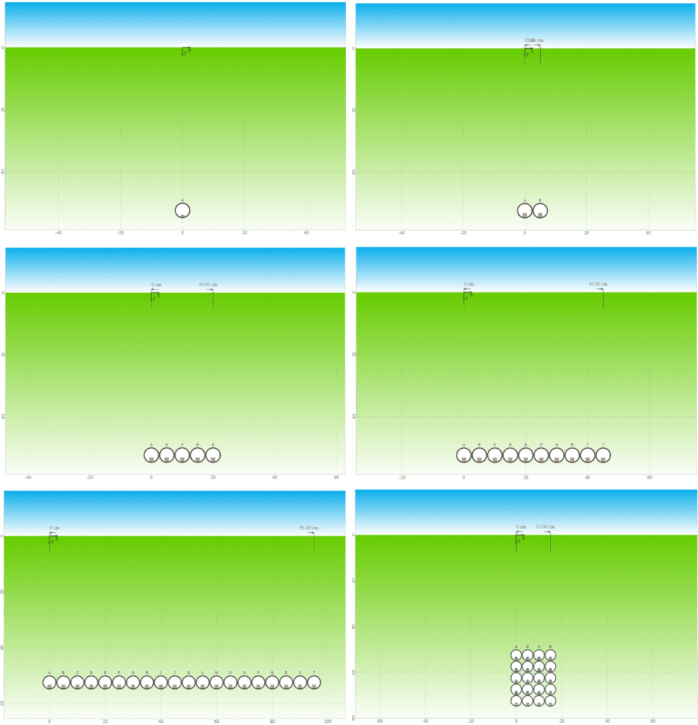
Figure 12: Case 4.1 – Trench with 1x circuit(top left), Case 4.2 – 4x circuits(top right),
Case 4.3 – 10x circuits (middle left), Case 4.4 – 20x circuits (middle right),
Case 4.5 – 40x circuits (bottom left), and Case 4.6 – 40x circuits arranged in five rows of eight (bottom right).
| Case | Max Cable Temp (IEC 60287) | % Increase | % of Max Allowable Temp |
| 4.1 – 1x circuit | 26.4°C | 0% | 29.33% |
| 4.2 – 4x circuits | 28.5°C | 8% | 31.67% |
| 4.3 – 10x circuits | 30.6°C | 16% | 34.00% |
| 4.4 – 20x circuits | 33.0°C | 25% | 36.67% |
| 4.5 – 40x circuits | 36.1°C | 37% | 40.11% |
| 4.6 – 40x circuits (five rows) | 42.0°C | 59% | 46.67% |
Even in the most extreme case (4.6), where the conduits are bunched in an arrangement with the minimum effective surface area, the highest temperature attained by any cable is still less than half of the maximum allowable. While the mutual thermal derating effect is not negligible, it has been demonstrated that for most conceivable quantities of lightly loaded cables the maximum temperature reached is well below the cable’s limit. Linear extrapolation indicates that under the conditions used in this particular example, the maximum sheath temperature of 90°C will not be reached until the number of adjacent circuits (laid flat in one row) is over 250. However, note that this number would be lower if the cables were installed in a common wiring enclosure and the numbers in this article should not be relied upon for verification purposes.
Conclusion
For the safe, efficient and reliable operation of electrical cables and the equipment they service, it is essential to verify that they are rated for the currents that they are designed to carry. AS/NZS 3008.1.1 offers a convenient, easily applicable and reliable method for calculating the current carrying capacity of buried cables in simple configurations within the assumptions of the standard, but more specialised methods are recommended for DC and intermittently loaded circuits that require the use of specific inputs based on cable installation methods, and are required for more complex trench designs that are not covered in the scope of AS/NZS 3008.1.1. The Cableizer software package utilises IEC 60287 calculations to verify the suitability of these circuits and trench designs, providing the most economically efficient solution while ensuring safety and reliability of the electrical system.
If you are not confident sizing cables, let GSES do the heavy lifting. We can produce detailed cable sizing and derating analysis tailored to your needs. Contact our design team at design@mindaro.energy or click the button below.