In a follow on to last years technical article on High Efficiency Cells: PERC and Half Cut, We have produced a video to easily understand how half cut solar cells work while shaded. The new developments and increasing complexity of solar panels makes this technology easily confused. Our latest video aims to clear things up below:
If you liked our video, please be sure to share it by copying this link or embed from YouTube directly! You can find approved solar panels (PV modules) for use in Australia on the clean energy council website.
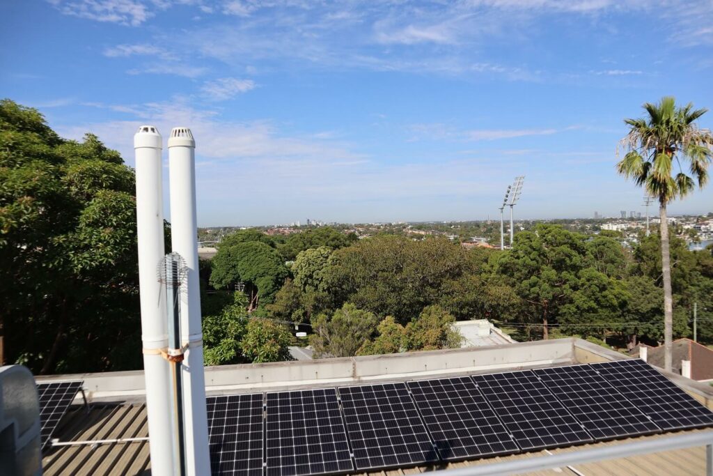
While this solar array is unfortunately located, it could have benefited from half-cut solar panels. This was noticed during one of our inspections for Asset Management Intelligence.
Adapted Video Transcript Below
Introduction
As the photovoltaic industry develops, new and exciting technology is introduced. One of the developments that has seen a recent increase in market share are half cut cell modules. These modules make use of namesake cells that are cut in half to improve performance and durability.
Half cut cell modules have quite a few advantages over their standard 60 and 72 cell counterparts. A commonly touted advantage is their superior performance under shaded conditions, however there are extra design and installation considerations that will need to be taken into account to ensure that the technology is best utilised. In this video we will explore how half cut cell modules operate in different shaded conditions and how they compare to standard PV modules.
Let’s say you have the following simplified 360W, 60 cell module installed in a portrait orientation. During the day this section of the panel experiences some unavoidable shading. Bypass diodes within the module allow for the current to be routed away from the individual cells in this substring, protecting it from hot spotting, but this also effectively lowers the panels output to 2/3s of its rated capacity, 240W.
Now, let’s look at a simplified 360W, 120 cell module, again in portrait orientation, with the same shading scenario. Half cut cells are configured in such a way that there are 6 substrings, with the cells in each half connected in series, and then each half is connected in parallel. The 3 bypass diodes are situated between each pair of substrings. What do you think the output will be?
240Watts
This answer may or may not have come as a surprise to you. Let’s have a closer look at what happens to half cut cells in different shading scenarios and how to make the most out of the technology.
Voltage and Current of half cut solar cells while shaded
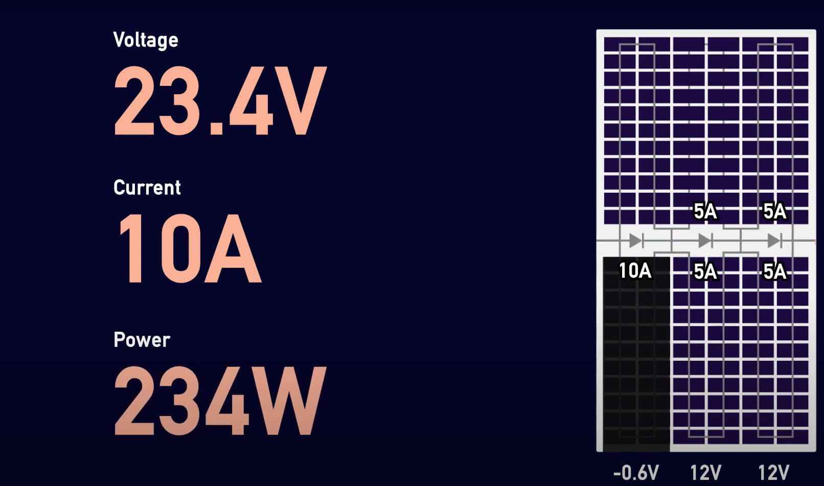
In the shaded string, the bypass diode is activated with a voltage drop of approximately 0.6V across it. The second and third substring will see 12V. This comes to a total of 23.4 V across the entire module.
Now let’s look at the current. For this half-cut module we are going to assume that each substring has a maximum 5A of current that can pass through it. In this case, 10A will first be diverted through the bypass diode in the shaded section. The current then splits to 5A through each unshaded substring, maintaining the total of 10A through the module. This means an output of 23.4V times 10A equaling 234W.
IV and Power Curves of shaded half cut solar cells
In the shaded string, the bypass diode is activated with a voltage drop of approximately 0.6V across it. The second and third substring will see 12V. This comes to a total of 23.4 V across the entire module.
Now let’s look at the current. For this half-cut module we are going to assume that each substring has a maximum 5A of current that can pass through it. In this case, 10A will first be diverted through the bypass diode in the shaded section. The current then splits to 5A through each unshaded substring, maintaining the total of 10A through the module. This means an output of 23.4V times 10A equaling 234W.
Comparing the I-V and power curve of both a standard cell module, and a half-cut cell module we can see that the maximum power output is the same.
So, what’s the difference between half-cut and standard modules?
Maximum Power Points (MPP) of half cut solar cells while shaded
1/3 Shading of lower module half
You probably have noticed that the half-cut cell has 2 maximum power peaks (MPP) in its power curve, a local maximum and a global maximum. This second peak, a local maximum in this case, comes about by operating at a lower current, while maintaining a relatively higher voltage in the unshaded substrings rather than activating the bypass diodes.
This is an option that is available to half-cut cells due to the parallel configuration of the two halves, and is in fact where half cut modules have the potential advantage over standard modules in shaded conditions. An inverter with global MPPT functionality will perform periodical sweeps across its range of current and voltage levels. This is done in order to avoid getting stuck at local maximum power points. The periodicity of these sweeps will depend on the manufacturer of the inverter and will result in some loss of power during the process. However, the trade-off is that the assurance that inverter will always seek out and operate at the globally maximum power point.
2/3 Shading of lower module half
Let’s have a closer look at what happens with the current and voltages in a more severe case of shading. This time 2/3rds of the bottom half of the module is covered. Note that even if the sub string within the module is partially shaded, for example by a leaf or by cloud cover, it will be to the same effect as if the entire string has been shaded.
In a standard cell, two bypass diodes will be activated, with a total voltage drop of 1.2V. With 12 V in the unshaded string there will be a total of 10.8V across the whole module. 10A of current will be produced by the unshaded string, and this equates to a power output of approximately 1/3 of the modules rated power, at 10A times 10.8V equalling 108W.
For a half-cut cell, the first MPP is similar to the standard cell. 10A will flow through the module, through the bypass diodes and then splitting into 5A in both sides of the unshaded string. Accounting for a voltage drop of 0.6V per activated diode, the module will have 10.8V. At this power point the module will be operating at 10A times 10.8V, equalling 108W of power.
The second maximum power point occurs at a lower current but a higher voltage. 5A of current will flow through the top two halves of the shaded strings instead of through the bypass diodes, splitting into 2.5A in both sides of the unshaded string. The voltage is maintained at 12 volts across each of the 3 strings for a total of 36V. This means that the output of the panel is approximately 2/3 of its rated power, at 5A times 36V equalling 180W.
Looking at the I-V and power curves for a simulated half-cut module, we can again see the two maximum power points – a local maximum and global maximum. In this case the difference between the peaks is more substantial, where running at a high current and a lower voltage is less beneficial than operating at a low current and higher voltage. As an inverter makes a full sweep of the operating range it will be able to identify the global maximum power point.
Overlaying the curves for the standard module, we can see that there is only one maximum power point, indicating an output that is approximately 1/3 of its rated power.
Half Shaded PV Module Scenario
Let’s examine one more example – where the shading has spanned across the lower bottom half of the module. Again, partial shading on a single string is equivalent to the entire string being shaded.
It is no surprise that a standard module will be outputting 0W in this scenario with all current being diverted through the bypass diodes. However, in a half-cut module, 5A can still flow through each substring of the unshaded half of the module. The voltage is 12V at each string to a total of 36V. This provides a power output of 5A times 36V equalling 180W, 50% of the modules rated power.
Looking at the I-V and power curves for both module types show that the half-cut cell can operate even when experiencing heavily shaded conditions.
Advantages of half cut solar cells while shaded
There are some clear advantages to half cut cells such as reduced resistive losses and reduced hot spotting impacts. However, a portrait install is necessary to make use of the advantages a half-cut cell provides in shaded conditions. Ideally you would orient the array so that shading occurs in the lower half of any given row of modules. Certain sites may not always have the room for a portrait install, and depending on the orientation of the site, the shading conditions and additional installation considerations may not warrant the increased costs that come with half cut modules. If a site does not experience heavy shading conditions there may not be much difference in the shaded performance between half-cut and standard modules. All of these considerations also need to be weighed up against the advantages that half cut cells provide, and now you’re better equipped to take advantage of them.