This article will look at the physics behind why it is necessary to derate electrical cables. It is the first in a series of articles covering cable sizing and deratings, so stay tuned for more on different methods to derate cables safely while maintaining cost effectiveness. Cable selection is one of the most crucial engineering problems in solar PV design. It has major implications on the overall cost of PV systems, performance, and safety in design of PV systems. Correct cable selection also ensures compliance with Australian and international standards.
Why derate electrical cables?
Cable derating ensures all factors which can increase the temperature experienced by the installation is properly accounted for when selecting cables to prevent damage to the cable insulation and reduce system losses. The derating factor is applied to reduce the cable’s current carrying capacity. For example, if a X-90 cable can carry 40A @90 degrees, there may be additional factors which requires the cable to be de-rated such that it carries only 30A@90 degrees in the installation.
Heat is the main reason why cables need to be derated. As current passes through the cable, heat is produced as a result of the electrical resistance of the wire. Multiple circuits running in close proximity can further increase the temperature of the conductors as a result of electromagnetic effects and physical proximity effects. When cables are arranged close to each other, cables have limited ability to dissipate heat and reach a hotter operating temperature. Linear resistance, the resistance of the cable per meter, is very small, but over a long cable run it is cumulative and results in voltage drop. As the cable temperature rises, the linear resistance also rises resulting in increased voltage drop and reduced system output.
All of these factors must be considered to calculate the cable derating that will maintain cable temperatures under design specifications and maximise the life of the cable insulation.
The following sections describe in more detail the various factors that induce heating in cables.
Joule Heating
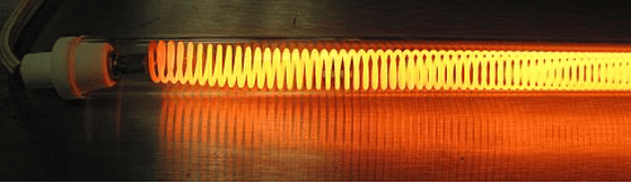
Figure 1: A coiled heating element heats up when a large amount of current passes through it due to Joule heating
(Source: Wikipedia commons)
When electricity moves through wires electrons are moving back and forth within the wire. These electrons are pulled along by an electric field, but they’re also bumping into the atoms that make up the wire. When an electron bumps into an atom, it transfers some of its kinetic energy to that atom. This results in the atoms heating up and the overall conductor temperature rising. This process is called Joule heating.
Joule heating can be described by Joule’s law, i.e. P = I2R, “I” is the Current flowing through the conductor and “R” is the conductor’s internal resistance.
Skin effect
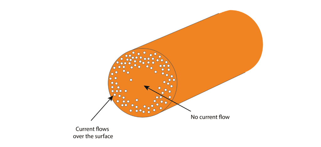
Figure 2: Skin Effect of AC current in a conductor
The resistance of a conductor depends on its cross-sectional area; a conductor with a larger area has more room for electrons to move, and therefore a lower resistance for a given length. Skin effect reduces the utilisation of the conductor’s cross section area. At high frequencies, alternating current (AC) does not penetrate deeply into conductors due to eddy currents induced in the material; it tends to flow near the surface. This is called the skin effect. Therefore, in a solid conductor such as a solid-core wire, current tends to flow in a layer or annulus at the surface, and less current flows through the material near the centre of the wire. This reduces the effective cross-sectional area of the wire. The lower the area for the current to flow through the higher the resistance of the wire. The higher the frequency of the current, the shallower the depth to which the current penetrates, more current is “crowded” into an increasingly smaller cross-sectional area near the surface, thus increasing AC resistance. Direct currents (DC) do not suffer from this effect as it has zero frequency.
Proximity Effect
In applications where multiple wires carrying the same alternating current lie side-by-side, or multiple cables installed within the same conduit or in adjacent conduits, the current carrying capacity of the installed cables will also decrease due to the proximity effect. The proximity effect causes additional current crowding, as discussed in the skin effect, resulting in an additional increase in the resistance of the wire. The proximity effect also increases with increase in current frequency.
For example, imagine two wires running parallel next to each other, with the same alternating current flowing in both wires in the same direction. The magnetic field of the adjacent wire will induce longitudinal eddy currents in the wire, which causes the current to be concentrated in a narrow strip on the side adjacent to the other wire. When the current in the wires flow in opposite directions, the currents are concentrated on the side farthest away from the adjacent wire. Both scenarios result in a similar current distribution as the skin effect; the current is crowded into a smaller cross-sectional area of the wire, so the resistance increases and thus the heat the cable generates also increases.
Installation Method
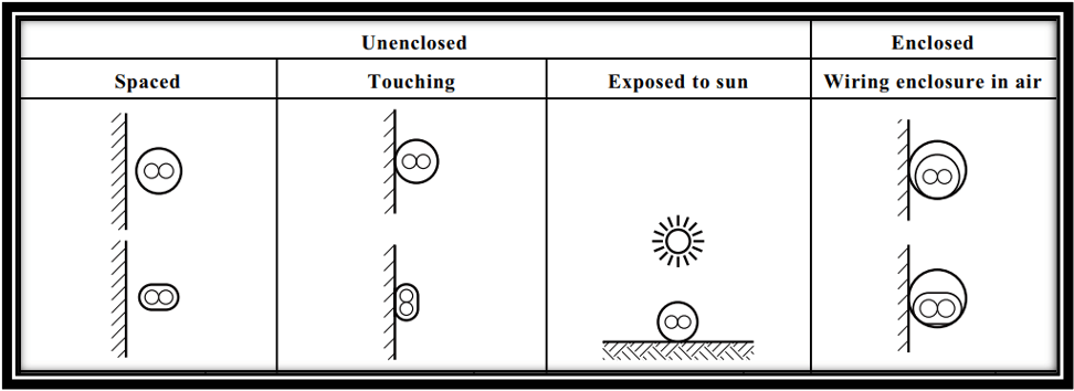
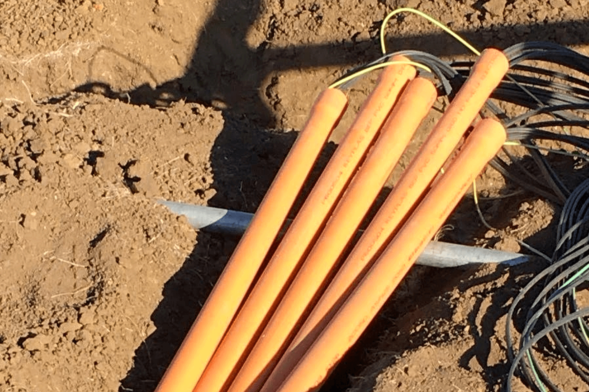
Figure 3: Types of installation Methods (Source: AS/NZS 3008.1.1:2017)
Cables can be installed in various methods; they can be installed in air, enclosed in conduits, or buried directly underground, to name a few. The installation method can affect the ampacity of the cables because as the material surrounding the cables changes, the ability of the cable to dissipate heat also changes. According the AS/NZS3008, the least amount of derating is required when the cables are installed in air, spaced away from a surface and other conductors. Conversely, the derating factor is highest when cables are buried underground in a wiring enclosure with other cables. Therefore, derating factors must be determined correctly corresponding with the type of installation method to reflect the actual current carrying capacity of the cables.
Cable Depth
When the burial depth of cables increases, the effective thermal resistance of the soil layer surrounding the cable increases. This is caused by the increased difficulty of the soil to dissipate the heat generated by the cables, and therefore the cables run hotter. To ensure the thermal limit of the insulation is not exceeded, the ampacity of a cable needs to decrease as the cable is buried more deeply in the soil. Therefore, cables that are buried at greater depths will be subjected to larger derating factors (smaller ampacity rating) than ones buried at shallow depths up to 0.5m.
Cables installed buried within a wiring enclosure underground will suffer from additional thermal resistance due to the presence of additional air surrounding the cables. Therefore, the cables have to be derated further to account for resistance due to the air envelope surrounding the cables.
Ambient Soil Temperature
Hot climatic regions have higher ambient soil temperatures, these temperatures can affect the cables installed within the soil. Warm soil surrounding the cables reduces the heat dissipation from the cables resulting in a hotter cable. This will in turn require derating of cables to reduce their current carrying capacity/ampacity.
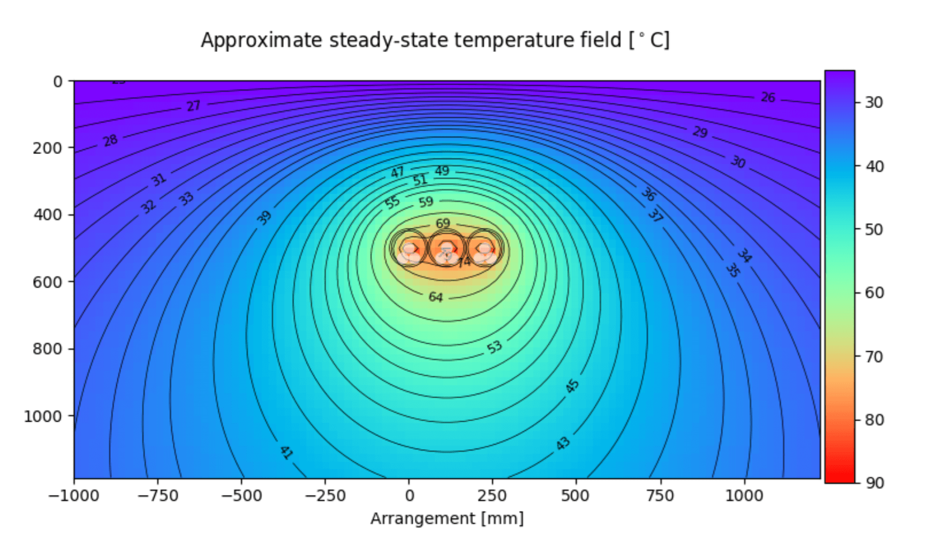 Figure 4: Effect of ambient soil temperature on cables buried directly in soil (generated by Cableizer)
Thermal Resistivity of Soil
Soil thermal resistivity is given as K.m/Watt it is a measure of how poorly a material conducts heat. It is the inverse of thermal conductivity. Underground buried cables transmit heat to the soil through the surface which is in contact with the soil. The thermal resistivity and moisture content of the soil is determined in a laboratory with samples being mechanically dried and measurements taken at different moisture content levels.
Moisture content of the soil affects its thermal resistivity, soil containing more moisture will have lower thermal resistivity as water is a good conductor of heat. On the other hand, dry soil will have higher thermal resistivity. Cables surrounded by soil which has higher thermal resistivity (e.g. porous/well drained/dry) will make it difficult for the cables to dissipate heat, which will result in cables heating up. This again means derating factors are needed to reduce the current carrying capacity to avoid hot cables. Soil with lower thermal resistivity (e.g. more moisture content) will be able to carry heat away from the cables much more easily and keep the cables cooler when they are under operation.
The catch here is that hot cables will dry out their surrounding soil, resulting in a higher soil resistance immediately around the cables or conduit. Additionally, the thermal resistivity of the soil changes through the seasons resulting in hotter soil in the summer months, corresponding with the season when solar arrays produce the most energy. As such, the worst-case conditions must be assumed when selecting cables and applying derating.
Load Factor (LF)
The load factor is the ratio between the average power (the energy supplied to the system) and the maximum power in a given period of time. The higher the LF value, the more the cable is utilised over a period of time, e.g. 24-hour. As the LF value approaches 1, the cable operates closer to the maximum power for longer. This means the steady state temperature of the cable and surrounding environment will be hotter. If the LF value is low, the heat generated by the cables can be dissipated through the local environment allowing the cables to operate at a lower temperature.
Cable Insulation
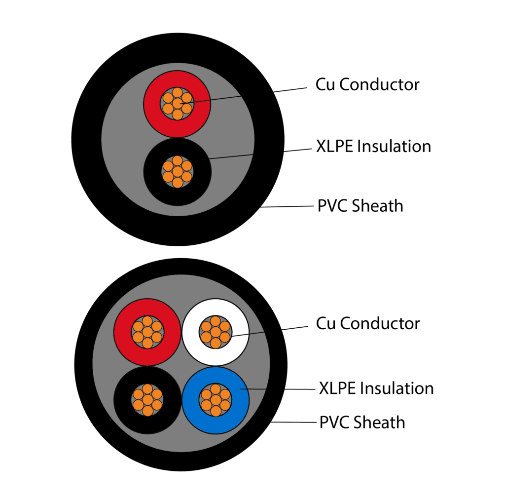
Figure 5: Cable Cross section showing insulation
The types of cable insulation also play an important role is determining the cable current carrying capacity and its ability to withstand harsh environmental temperatures; a 90°C rated insulation will have a higher current carrying capacity than a 75°C insulation. Therefore, if the installation will be exposed to high temperature but a high current carrying capacity must be maintained, its ideal to use the higher rated cable insulation so cables do not melt under normal operating conditions.
Conclusion
Due to the above mentioned electrical and environmental factors, it is necessary for us to identify all the factors that before attempting to derate electrical cables, and apply the appropriate physical effects such that the cables installed are fit for purpose for the installation.
GSES provides a range of competitively priced design services including; advanced cable sizing and selection, pre-feasibility system studies, concept design, construction design, and post installation inspection services. Please contact design@mindaro.energy for a copy of our capability statement or to learn more about our services. Furthermore, check out our technical articles on cable deratings on our technical article section; link here: https://www.gses.com.au/resources/technical-articles/.