This article will give you an overview and examples of DC cable sizing using the standard AS/NZS 3008. Cable sizing is one of the most crucial engineering problems in PV system design. It has major implications on the overall cost, performance, and safety in design of PV systems. Correct cable selection also ensures compliance with Australian and international standards.
This article explores DC cable selection using Australian/New Zealand standard AS/NZS 3008.1.1:2017 Cables for alternating voltages up to and including 0.6/1 kV—Typical Australian installation conditions (henceforth referred to as “AS/NZS 3008”). This Standard is commonly referenced in PV design, but it also has broad applications in electrical engineering.
AS/NZS 3008 will be discussed in regard to DC cable selection for PV systems. This article explains GSES’ interpretation of Tables 5 to 15, Tables 22 to 29, and Tables 34 to 39 in AS/NZS 3008, and notes installation conditions under which AS/NZS 3008 cannot be applied, and where alternative specifications are required. If everything seems a bit complicated, let our engineers take care of cable sizing for you!
What is AS/NZS 3008?
AS/NZS 3008.1.1 is an Australian/New Zealand standard which defines electrical properties (namely ampacity) of cables under typical Australian conditions and installation arrangements. It applies to Alternating Current (AC) systems up to and including 0.6/1.0 kV. Despite its title including ‘alternating voltages’, AS/NZS 3008 can also be applied to DC installations.
AS/NZS 3008 is important because it allows us to size cables in a way that minimises system cost while still satisfying the following circuit requirements:
- Current-carrying capacity (CCC). Also known as ampacity, this is the maximum continuous current that a conductor can carry under its installation conditions without exceeding its rated temperature. An adequate CCC is required for all installations, otherwise cable damage and safety issues can occur.
- Voltage drop (Vd). Voltage drop is the decrease of voltage along the cable run due to the cable’s internal resistance. Voltage drops are undesirable because generated energy is lost as heat. Therefore, voltage drop must be considered when sizing PV cables to avoid degraded performance.
- Short-circuit temperature limit. This is the temperature that cables can adequately handle when exposed to their maximum prospective short circuit current. AS/NZS 5033:2014 sets out the calculation of prospective short circuit currents in PV systems. As PV systems are a current-limited source, this is not a limiting factor in DC cable selection.
Derating Tables in AS/NZS 3008
The following derating Tables from AS/NZS 3008 are used in subsequent sections of this article:
- Table 22. Derating factors for bunched circuits – in air or in wiring enclosures.
- Table 23. Derating factors for circuits – single-core – in trays, racks, cleats, or other supports in air.
- Table 24. Derating factors for circuits – multicore – in trays, racks, cleats, or other supports in air.
- Table 25(1) and Table 25(2). Derating factors for groups of circuits – buried direct in ground.
- Table 26(1) and Table 26(2). Derating factors for groups of circuits – in underground wiring enclosures.
- Table 27(1). Rating factors – cables in air or heated concrete slabs.
- Table 27(2). Rating factors – cables buried direct in ground or in underground wiring enclosures.
- Table 28(1) and 28(2). Rating factors – depth of laying.
- Table 29. Thermal resistivity of soil.
Tables 22-26 can be loosely considered as derating factors resulting from installation methods, and Tables 27-29 can be loosely considered as rating factors which account for the environmental effects to which the cables are exposed.
Cable Sizing using AS/NZS 3008
The following method can be used to size cables according to AS/NZS 3008. A worked example is included for clarity, as detailed in Figure 1 below. In this example, a typical combiner box is fed by 16 strings of 18x 380W modules. Each string is protected by a 16A fuse (sized according to AS/NZS 5033 Clauses 3.3.4 and 3.3.5), and the array cable does not have a fuse. For the purposes of this example, the system will have the following constraints:
- Module Short Circuit Current Isc: 10.05A
- Module MPP Voltage Vmp: 40.03V
- Module MPP Current Imp: 9.50A
- Module leads: 4mm², 1.2m long
- Module Series Fuse Rating: 20A
- Selected String Fuse: 16A
- String cable run (assumed for all strings): 40m in wiring enclosure (i.e. enclosed, touching)
- Array cable run: 120m in underground wiring enclosure with 0.6m depth of coverage
- Maximum ambient air temperature: 50°C
- Maximum ambient soil temperature: 35°C
- Soil thermal resistivity: 1.5°C.m/W
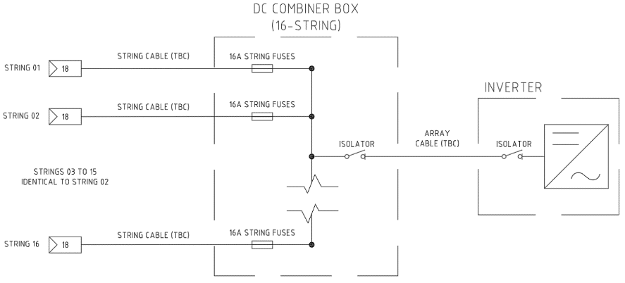
Figure 1: Initial System Configuration
The string and array cables will first be sized for their current-carrying capacity, accounting for relevant derating factors. Then, after both string and array cables have been initially sized, the worst-case voltage drop of the system will be calculated to determine whether any cables need to be upsized. As generic equipment is used, no consideration will be given to cable size limits on the input terminals of the inverter, isolators, or other equipment.

String circuit
Sizing string cables is often the first step in the cable selection process. In most cases, the CCC of common PV string cables (4mm² to 16mm²) exceed their rated operational current by a significant margin. In extreme cases, the derating factors listed in Tables 22-26 may not apply as, according to Clause 3.5.2.2 (d) of AS/NZS 3008, Tables 22-26 are not applicable for circuits operating at less than 35% of their current-carrying capacity.
While environmental deratings under Tables 27-29 may decrease a cable’s current carrying capacity, this is often insufficient to push the cable loading over the 35% threshold. Instead, the primary factor affecting string sizing will often be voltage drop.
For the given example, string overcurrent protection is present, and as such the string circuits must be designed to sustain an operational current of at least the string fuse rating (i.e. 16A). This is in accordance with AS/NZS 5033:2014 Table 4.2.
For this example, 6mm² PV twin (i.e. two single-core) cables are selected for the purposes of cable selection using AS/NZS 3008. Considering the temperature limits of equipment terminals and to maintain high conductivity in the cables, a 90°C temperature limit has been determined for the PV cables. Referring to Table 5 of AS/NZS 3008, we see that the CCC of two single-core flexible 6mm² cables is 46A (in touching configuration).
Tables 22 to 26 are then checked to calculate temperature derating from cable installation conditions. Of these, Table 22 is the most applicable – in particular, we look at Row 2 “Bunched on a surface or enclosed”. As we have 16 string circuits, we assume that all of these will be contained within the same wiring enclosure. As a result, the derating factor from this Table is 0.41.
Next, we check Tables 27 to 29 and apply the relevant environmental derating factors to string cables. From these, only Table 27(1) is applicable to our string cables, which are installed above-ground. From here, we find that the derating factor on our strings as a result of ambient air temperature is 0.88 (50°C ambient temperature for cables rated at 90°C). Multiplying this by the previously calculated derating, we find a total derating of 0.3608. Multiplying our original CCC by this value, we achieve a final derated CCC of 16.597A, slightly above the fuse rating.
This is a reasonable result, and as such we initially accept 6mm² twin cables for our strings.
Array circuit
Sizing array cables is generally a more complex process, as these are often designed to carry currents much closer to their rated values. In this example, there is no overcurrent protection on the array circuit, so per AS/NZS 5033:2014 Table 4.2, the circuit must be sized to carry 1.25 times the maximum short circuit current on the conductors.
As before, we begin by calculating the design current for the array circuit. Here, this is simply 16 times the short-circuit current multiplied by 1.25 as per AS/NZS 5033:2014 Table 4.2, i.e. 201A.
Before selecting a cable based on the CCC, we first calculate the cumulative derating factor on our array circuits, then size our cables accordingly. According to Clause 2.3, this is done by taking the appropriate derating factor from Tables 22 to 26, and multiplying this by any relevant derating factors from Tables 27-29.
In this case, the array circuit is installed underground in a conduit, so the most applicable condition will be “bunched on a surface or enclosed” per Table 22. Since there is only one circuit in the conduit, Table 22 provides a derating factor of 1.00, meaning there is effectively no derating applied to the CCC. We then go through Tables 27-29 and record any applicable deratings, which we will later multiply for a cumulative derating factor.
- Table 27(2) defines derating from soil ambient temperature. For a conductor rated at 90° and a soil ambient temperature of 35°C (assuming worst case), the Table gives a derating of 0.93.
- Table 28(2) derating from depth of laying for cables in underground wiring enclosures. For single-core cables buried at 0.6m, the Table gives a derating of 0.98.
- Table 29 derating from thermal resistivity of soil (i.e. how efficiently heat can dissipate through the soil). For two single-core cables in a wiring enclosure, with a thermal resistivity of 1.5°C.m/W, the table gives a derating of 0.94.
Now that we have all relevant derating factors, we can multiply them together to find the total derating on the array circuit – this comes out at approximately 0.857. We can then divide our array design current (201A) by the combined derating factor to produce the minimum CCC for our array circuit, which becomes 234.5A.
Finally, we refer to Tables 5-14 to find an appropriate cable that meets this CCC. Table 5, describing two single-core cables (X-90 insulated), gives a CCC of 276A for flexible 95mm² cables (installed with one circuit in an underground wiring enclosure). Therefore, we initially choose 95mm² cables for our array.
Voltage Drop
Now that we have initial cables for both strings and array, we need to check that the voltage drop (Vd) for our system is acceptable. According to AS/NZS 5033:2014 Clause 2.1.10 (c), voltage drop for a PV circuit should not exceed 3% of array maximum power point voltage at STC conditions (Vmp).
The following equation is adapted from Section 4.3 of AS/NZS 3008, and can be used to calculate voltage drop (as a percentage) on DC circuits:
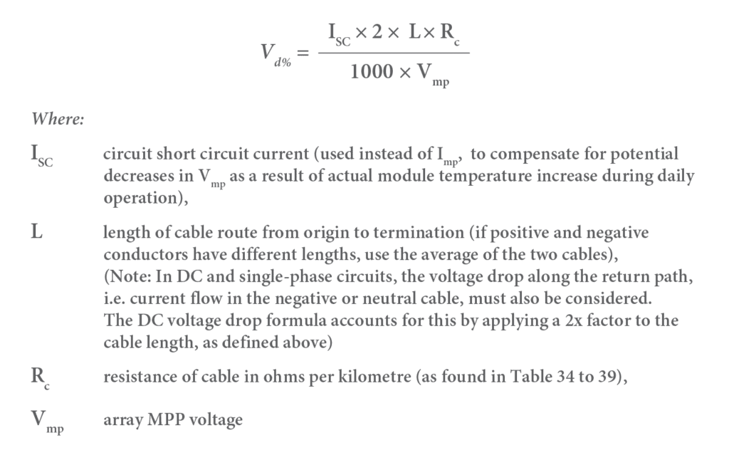
The use of Isc in these calculations is intentionally conservative when compared to the method used in much of the industry. Isc is used in place of Imp(STC) to account for daily variations in Vmp, and is used to ensure that voltage drop will be within acceptable limits in the worst case.
Referring to Tables 34 to 39 (specifically Table 37), we can take Rc values for our cables, and calculate a Vd for each. The Rc values are: 6.31 ohm/km for 4mm² module leads, 4.21 ohm/km for 6mm² string cables, and 0.264 ohm/km for 95mm² array cables. We can then plug these into the above formula to calculate Vd for each conductor. These become 0.38% for 4mm² module leads, 0.47% for 6mm² string cables, and 1.414% for 95mm² array cables. Summing these values, we find the total Vd for all conductors in series to be 2.264%, below our system limit.
The final system configuration will look like this:
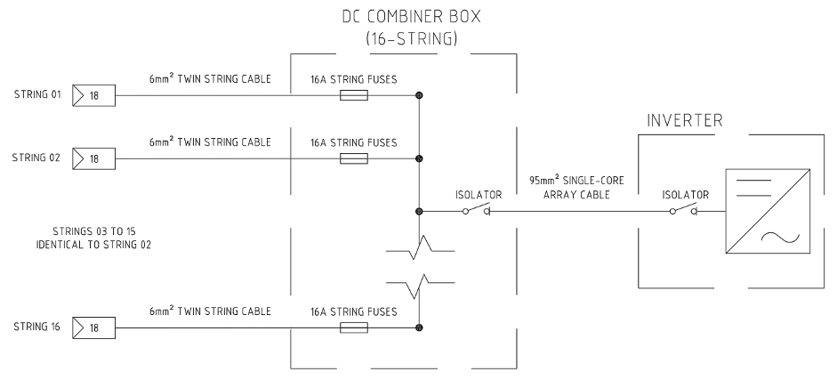
Figure 2: Final System Configuration
Scope and Limitations of AS/NZS 3008
As demonstrated, AS/NZS 3008 is an excellent tool for cable sizing and selection. The numerous tables included in AS/NZS 3008 cover a wide variety of installation conditions, and for many systems AS/NZS 3008 can be applied quickly and easily. However, it has several limitations when being applied to PV arrays, particularly utility scale, which are important to keep in mind. These limitations include the following:
- Derating factors. When considering derating factors, Tables 23 to 26 do not describe systems with large numbers (>20) of conductors, e.g. utility scale PV systems.
- Multi-tiered trenches. When designing underground cable systems, AS/NZS 3008 does not describe deratings for multi-tiered trenches (per Clause 1.3(c)).
- System voltages. AS/NZS 3008 does not describe cables rated above 0.6/1kV.
- Temperatures inside equipment. AS/NZS 3008 does not directly consider the effects of temperature rise inside enclosures or switchboards, or at the terminals of equipment as a result of cable design. Therefore, additional consideration must be given to switchboard and DC isolator or combiner box designs, including the devices within those enclosures and their applicable thermal limits.
- Cyclical/intermittent loading. AS/NZS 3008 allows for varying loads on different cables (as per Clause 3.5.6) but does not describe a method for the application of cyclically or intermittently loaded cables.
- Thermal resistivity. AS/NZS 3008 assumes that the effective thermal resistivity of soil for underground cables is constant at all depths. This cannot always be assumed in real life situations.
Cable Sizing outside of AS/NZS 3008
There are several methods that can be used to address the aforementioned issues. This list is not exhaustive, but describes industry-standard approaches:
- Thermal modelling software. Thermal analysis software can be used to model a cable’s thermal performance under specific operating conditions. These modelling programs can simulate a higher level of complexity and accuracy than AS/NZS 3008, and allow many of the AS/NZS 3008 limitations to be directly addressed.
- ERA Report 69-30 Current rating standards for distribution cables. This report, particularly Parts III and V, gives information on several areas that are not covered by AS/NZS 3008, particularly group rating factors for underground cables laid in tier formation.
- International standards According to Clause 1.3 of AS/NZS 3008, CCCs may also be determined using IEC 60287 in conjunction with IEC 60364-5-52.
Conclusions on cable sizing with AS/NZS 3008
Cable Sizing with AS/NZS 3008 is an important skill when designing PV systems in Australia. It covers a wide variety of installation conditions, and allows system designers to size cables with relative efficiency. However, it also has several limitations which need to be understood while designing, to ensure that the system is compliant with Australian regulations and standards, and the design results in safe and efficient cable selections. GSES recommends consulting with cable suppliers and manufacturers regarding how to apply AS/NZS 3008 Clause 1.3, especially where to use alternative standards and reports to size and derate cables.
If you are not confident sizing cables, let GSES do the heavy lifting. We can produce detailed cable sizing and derating analysis tailored to your needs. Contact our design team at design@mindaro.energy or click the button below.