The latest version of the Australian and New Zealand Standard: Grid connection of energy system via inverters – Installation requirements (AS/NZS 4777.1:2016) was released on 30 September 2016. There is a transition period of 6 months, therefore this standard will come into effect at the end of this month (30th March 2017).
AS /NZS 4777.1:2016 supersedes AS/NZS 4777.1: 2005. As grid connection of inverter energy systems (IES) have seen many changes in the past 11 years, the new standard now better reflects current PV system installation practices and configurations, especially in respect to commercial PV system installations, and PV system installations with battery energy storage systems. Standards updates like these are a necessary hurdle for an industry that is constantly growing in size and experience, and that encounters an ever broadening range of products. To assist the industry with this, Global Sustainable Energy Solutions (GSES), with its extensive experience in PV training, design and inspections, is regularly involved in discussions over practical methods that installers can use to implement the latest standards and guidelines.
While this standard has more than quadrupled in contents, many new requirements are simply adopting or clarifying industry practices which are already commonplace. This article describes the key updates to the standard and what they mean for installers. Please note that not all changes are included here, so GSES recommends that installers read the standard for themselves to ensure they are aware of all current requirements.
Maximum DC Voltage and Restricted Access
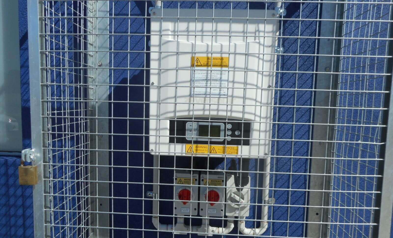
The requirement of a maximum 600V DC voltage in domestic installations and restricted access for non-domestic systems with over 600V DC is not new to PV system installers; this requirement was introduced in AS/NZS 5033:2012 and further clarified in AS/NZS 5033:2014. However, the scope of AS/NZS 5033:2014 is for PV arrays only. With the inclusion of this requirement in AS/NZS 4777.1:2016, this means that this requirement would apply to any DC power source connected to an IES, whether it be in the form of batteries or a PV array. The definition of restricted access is consistent with AS/NZS 5033:2014, where if HD conduit is used on all accessible cabling, up to and including the inverter terminals, and the DC isolators and protection devices are in enclosures only accessible with a tool, then there is no need for additional barriers. However, if a lockable room is used for providing restricted access then these precautions are not necessary. For more information, see AS/NZS 4777.1:2016 1.3.29 and 2.3.
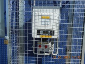
Figure 1: Cage installed to achieve restricted access. Cages like this may no longer be necessary.
Connector or coupling connection to the IES
Where connection to the inverter is by flex cable and connector (E.g. MC4 connectors), cables are required to be secured in such a way to prevent inadvertent disconnection and mechanical stress. The standard allows for a maximum of 300mm unsupported cables. This requirement has been part of the Clean Energy Council’s PV system install and supervise guideline and therefore would be a familiar requirement to most installers. The standard also specifies that only connectors and couplers of the make, type and model specified by the manufacturer can be used at inverter port connections. For more information, see AS/NZS 4777.1:2016 3.2.3.
![]()
Figure 2: conduit and strain protection installed to prevent inadvertent disconnection and mechanical stress.
Voltage rise
AS/NZS 4777.1:2016 now specifies that the overall voltage rise from the point of supply to the inverter AC terminal to be 2% or less of the nominal voltage at the point of supply. Some examples have been provided in Appendix C to provide guidance on how voltage rise can be calculated for a single phase system, three phase system, or an installation with multiple inverters.
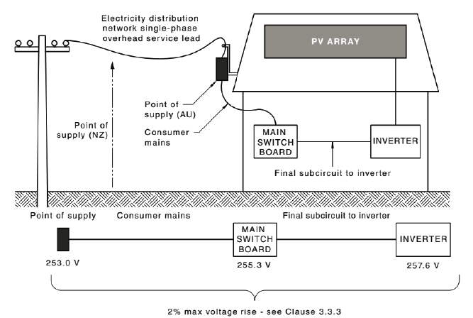
Figure 3: Figure C1 from AS/NZS 4777.1:2016 showing example of application of voltage rise for IES’s.
RCDs as isolation means for grid-connect only inverters
Recent changes seen in AS/NZS 4777.1:2016 and AS/NZS 4777.2:2015 mean that use of a dedicated RCD between the IES and the MSB, is now permitted as a means to meet mechanical cable protection requirements for grid-connect only inverters. This can allow for slightly easier AC cable installation to grid-connect only inverters. However, this configuration is not allowed on a multiple mode inverter with standalone functionality in use.
AS4777.1: 2016 explicitly excludes the use of RCD for this purpose with multimode inverters with a stand-alone port. This is because the RCD will typically switch both Active and Neutral conductors, thus breaking the Neutral to MEN connection. If the multiple mode inverter disconnects the stand-alone port neutral conductor from the main installation neutral when it switches to stand-alone mode, it will remove both the earth reference required for RCDs (whether RCCB or RCBO) to operate in earth leakage mode, which can then create shock hazards.
For more information, see AS.NZS 4777.1:2016 3.4.5 and 5.4.3, and GSES’ previous article, Connection of Inverter Energy Systems to the Grid: New requirements surround residual current devices.
AC and DC segregations clearly defined
Similar to the requirements for restricted access, AS/NZS 4777.1 now also outlines requirements for AC and DC segregation consistent with AS/NZS 5033:2014. This is helpful for installations which are not covered by AS/NZS 5033:2014, such as battery storage systems.
Insulation barriers between AC and DC must be equivalent to double insulation and IP4X. The only exception to this is when cabling is outside enclosures, where 50 mm separation can be used instead. Within 50 mm, an insulation barrier will again be required.
A simple way to abide by these requirements is to install AC and DC in separate enclosures and separate conduit (Figure 2). Installing AC and DC in the same enclosure, with a compliant insulation barrier, is difficult to achieve. The IP4X rating requires the barrier to prevent penetration of objects with a 1 mm diameter or greater. In addition to this, AC and DC switchgear cannot share the same mounting rail unless it is made from a non-conductive material. It will be difficult for barriers installed within enclosures to follow these requirements unless purpose-made enclosures are produced that comply.
For more information, see AS/NZS 4777.1:2016 5.2
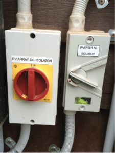
Figure 4: AC and DC installed in separate conduit and enclosures. This is the most effective way to achieve compliant insulation barriers between AC and DC circuits.
Multiple Inverter Energy Systems
AS/NZS 4777.1:2016 introduces requirements for installations where multiple inverters are installed. The requirements aim to minimise the number of main switches for inverter supply to avoid confusion and aid in effective isolation of IES’s on site. Where IES’s are connected to switchboards with loads, their isolation switches, labelled as ‘Main Switch (Inverter Supply)’, are required to be grouped. If there are more than two IES’s connected to switchboard with loads, then a single main switch (inverter supply) is required to be used to isolate all connected IES’s. In the latter case, a separate distribution board should be provided for isolation of individual IES’s. Where IES’s are connected to dedicated switchboards without loads, the distribution switchboard is required to have a single isolator (labelled normal supply, or submains supply) and inverter AC isolators for each IES. In all cases, isolation switches need to be clearly labelled to identify the inverter which the
switch isolates.
For more information, see AS/NZS 4777.1:2016 5.5.
Signage
There have been changes in signage wording and colouring. Additional signage requirements have also been introduced for installations with multiple IES’s and for installations with multiple mode inverters and battery energy storage systems. Main switch of IES’s are now required to be labelled ‘Main Switch (Inverter Supply)’. This reflects the fact that the energy source may be from batteries or from PV arrays. There is also a wording change to the labelling of main switch which provides isolation from the grid to ‘Main Switch (Grid Supply)’. The label, ‘Main Switch (Normal Supply)’ will instead be required on distribution boards to indicate the isolation point for the normal supply to the distribution board. Additional warning signs apply for multiple mode inverters with stand-alone functionality. This sign needs to be installed at the main switchboard and any intermediate distribution boards, and needs to include the text “Neutral and earth circuits may be live under fault conditions”. The main switch for the stand-alone port of multiple mode inverters need to be clearly labelled ‘Main Switch
(Stand-Alone Supply).
Although installing the correct labelling and signage is important, where they are displayed is vital for achieving their purpose. AS/NZS 4777.1:2016 has included several adjustments to the labelling and signage requirements that help ensure they are installed in practical and visible locations. For example, at sites installed with energy storage systems, the green reflector signs with the letters ‘ES’ need to be installed on or immediately adjacent to the meter box and main switchboard so that they are visible to approaching emergency workers. Installers should ensure that they review AS/NZS 4777.1:2016 6 Signs and Labels, to confirm they are installing labels in appropriate locations.
For more information, see AS/NZS 5033:2014 6.
Keeping on top of changes in the industry
To assist PV installers in keeping on top of changes in the industry, like these necessary standards updates, GSES are releasing informative animations, subscribe to our channel here!
To learn more we offer Nationally Recognised Accreditation courses, enrol now to stay at the forefront of the industry!