Introduction
There are two major problems that can occur in an electrical system – open circuits and short circuits. Of the two, the latter has more detrimental effects on the system. A short circuit fault is an abnormal or unintended connection of live elements touching each other or to earth. Typically, short circuit faults are broadly classified into two categories:
- Symmetrical Faults
- Three phase faults (3L)
- Three phase to ground faults (3L-G)
- Asymmetrical Faults
- Single line to ground fault (L-G)
- Line to Line fault (L-L)
- Double Line to ground fault (L-L-G)
Each of these fault types will have different short circuit currents even when they occur at the same location on the electrical installation.
The calculation of short-circuit currents are of two types and essential for two main purposes:
- Maximum short-circuit current– This determines the ratings or necessary capacity of electrical equipment connected at that location.
- Minimum short-circuit current– This is essential to validate the sensitivity of the protection devices and the application/selection of fuses that have minimum breaking current limitations.
Importance of voltage factor (c)
It is a factor used for the determination of equivalent source voltage. The introduction of a voltage factor is important as it compensates for any voltage variations depending on time and location and assumptions during calculation.
As per AS 3851: 1991 Cl. 5, the voltage factor to be applied shall be selected as follows:
Table 1: Value of voltage factor (c)for calculation of short-circuit current (Source: AS 3851: 1991)
| Nominal system voltage (Un) | Voltage factor (c) | |
| Maximum short-circuit current | Minimum short-circuit current | |
| ≤ 650 V | 1.06 | 0.94 |
| > 650 V |  | 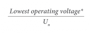 |
Note:Highest voltage of the system as defined in AS 1824.1.
*Line-to line voltage values to be considered. In the absence of an established voltage, assume c = 0.9
The short circuits can be calculated by representing the electrical system as an equivalent voltage source and the impedances of the elements in the system. Our electrical system consists of various voltage levels to facilitate transfer of power from the generation point to the load centre efficiently via step-up and step-down transformers. As all electrical equipment has some form of internal resistance or impedance whether they are AC or DC circuits, these values affect the magnitude of any given fault in an electrical system. The values of impedances (defined as ‘Z’ on AC circuits) of all the equipment are determined based on KV and KVA ratings. For the ease of calculation of the short circuits, a calculation method called per unit (pu) system is employed.
Per unit (pu) system for impedance calculation
The per unit system unifies all the values of a power system to a common base so they can be easily compared across the entire system. To begin with, a three-phase power base (Sbase) and line-line voltage base (Vbase) is defined for the system. We can then calculate the current and impedance bases using the following equations:


Any power system value can be converted to per unit by dividing the value by the base of the value

Similarly, a pu value can be converted to its actual value by multiplying it to the base value of that quantity.
In the calculation, it may often happen that the rated voltage of the equipment is different from the base voltage that you have pre-defined. To convert impedances from one base to another, the following equations may be used:

For grid connected PV systems, the inverters are connected at the 400 V LV side of the distribution transformers. The short-circuit rating of the main switch board (MSB) connected to the transformer LV is close to the let-through fault current of a transformer.
Sample Calculation
For example, consider a 750 kVA, 22/0.4 kV distribution transformer with an impedance (Z) of 4%.


Implementation of short-circuit current calculations using ETAP® software
The ETAP® software package can be used to evaluate the maximum and minimum short-circuit levels at the existing distribution board before and after the connection of PV system.
Consider a small-scale industrial facility receiving power from a 1500 kVA distribution transformer. Based on the site-inspection and design considerations, the PV system (Array and inverter) is selected.
The entire electrical system has to be modelled in the software. In order to model the system accurately, various design and electrical parameters are to be inserted in the editor window of each element as shown in Figure 1.
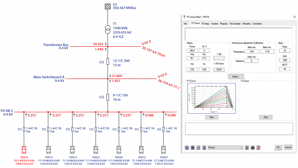
Figure 1: PV Array Editor view taken from ETAP® software
The software calculates the symmetrical (three-phase) and unsymmetrical faults (L-G, L-L, L-L-G) on the system. The value of c-factor can be manually adjusted according to the system requirements. The simulation results can be observed as shown in Figure 2. The values in red show the contribution from the upstream network along with the additional contribution from the PV system with arrows depicting the direction of current flow at each board. The maximum and minimum fault currents thus obtained can be used to determine circuit breaker device ratings and further undertake protection coordination study for reliable discrimination between the devices. (For more information on electrical coordination and discrimination see our article on this topic HERE).
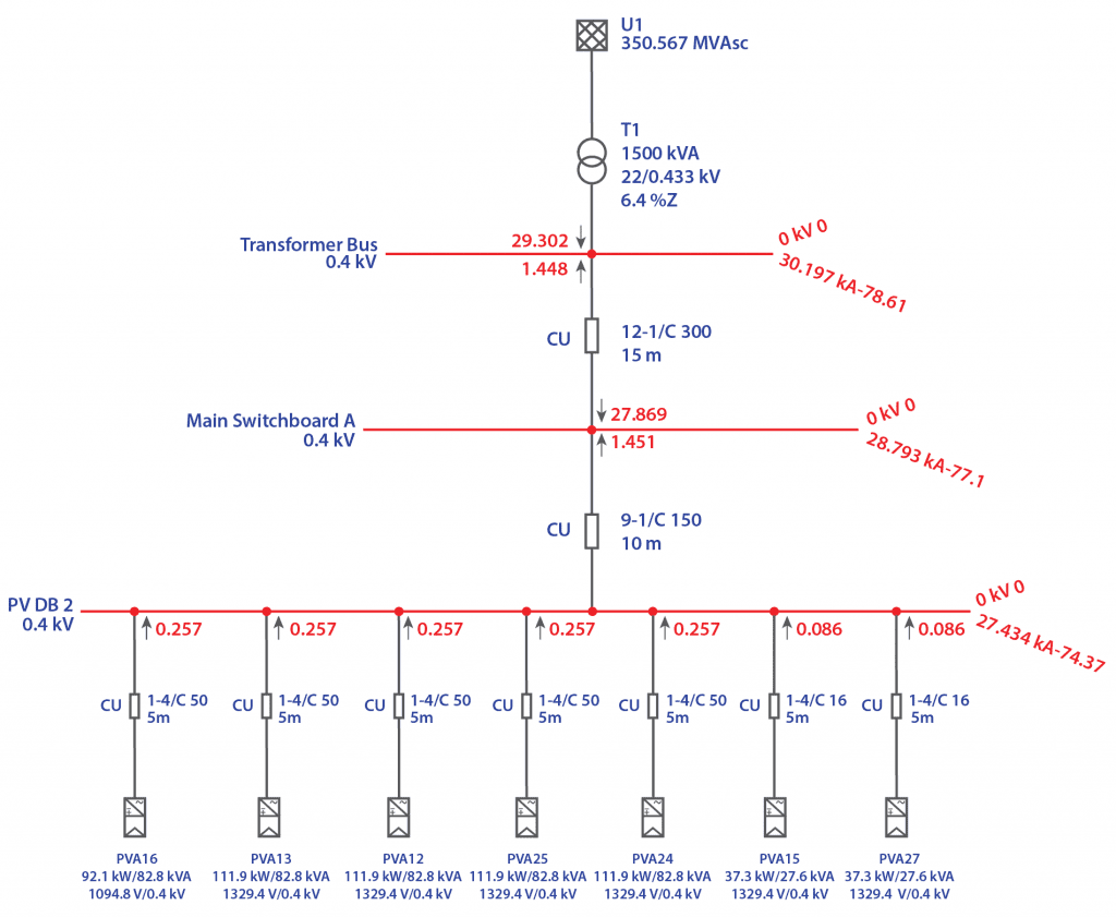
Figure 2: Three-phase fault results from ETAP® software
Conclusion
As knowledge of fault currents is essential before determining the equipment ratings such as circuit breakers, cables etc, short-circuit analysis has become a mandatory step for many DNSPs prior to connection of a PV system to the grid. Sizing of equipment with adequate short circuit withstand capacity improves the life of the equipment thus enhancing system reliability. Protection coordination studies is also important during design phase with network applications becoming increasingly strict.
GSES provides design and consultancy services which including the application to connect with various DNSPs throughout Australia. GSES offers services such as protection coordination studies, detailed three-phase and single-phase fault analysis and earth fault studies. For more details contact the design team at design@mindaro.energy or give us a call at +61 2 9024 5312.