
Introduction
Protection coordination/selectivity
With utilities and DNSPs becoming strict on network applications, protection coordination studies are becoming more prevalent and often are requirements before connecting and energizing a grid connected PV system. Therefore, it is important that circuit breaker and other protective device coordination is achieved before installing the system, as this can cause unwanted issues for the network and the customer.
Sizing circuit breakers according to system current and voltage specifications should not be the only criteria considered when selecting the protective devices. Although important, it is also crucial for system functionality to ensure that the chosen breakers discriminate with one another and those that are already existing. In AS/NZS 3000:2018, clause 2.5.7.2.1 defines discrimination (selectivity) to depend on the operating specifications of two or more protective devices such that the downstream device shall operate for a given fault current whilst the protection device upstream does not. As per the AS/NZS 3000:2018 standard, selectivity is a mandatory requirement in all electrical systems so that nuisance tripping of the protective devices can be minimised.
Protection coordination is important for the protection of the load and system components. It ensures that the downtime on the healthy circuits in a given system can be reduced and minimised.
Importance/relevance
Figure 1 below is taken from AS/NZS 3008:2018 and can be used to explain the importance of coordination protective devices (PD), such as circuit breakers. If there is a fault downstream of PD 2 (as shown in Figure 1), it is important that the closest device to this fault trips first, as to avoid nuisance tripping on healthy parts in a circuit. If PD 1 and 2 were not successfully coordinated, and PD 1 tripped before PD 2, then the entire circuit down stream of this would be de-energised. This is referred to as nuisance tripping, as the circuit containing PD 3 has been de-energised, even though the fault is downstream of the circuit with PD 2.
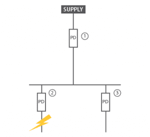
Figure 1: Circuit schematic from AS/NZS 3000:2018
Circuit breaker time-current curves
Each circuit breaker has its own unique time-current curve that needs to be coordinated effectively with other protective devices to ensure successful device discrimination. Each curve has an upper and lower boundary, creating a region that illustrates the expected tripping time of a circuit breaker when a corresponding current is reached. This can be seen in Figure 2, where the time-current curve of a 160A breaker is shown using a software called PowerCAD®.
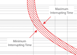
Figure 2: Section of a time-current curve of a 160A breaker from PowerCAD® software
These curves contain two distinct regions, overload and instantaneous, whilst also containing an indication of the breakers’ fault current rating. When in the overload region, circuit breakers can remain closed for periods of up to a few minutes. As the current increases along the curve, the time taken for the circuit breaker to trip and open the circuit reduces significantly. In the instantaneous region, breakers will typically open within milliseconds of sensing such a high current. Time-current curves will also convey the fault rating of the circuit breaker, where the device will shut off instantly in the event of a fault current, if the breaker has been rated to handle such a high current value. These regions can be found in the time-current curve of a 160A breaker from PowerCAD® shown in Figure 3.
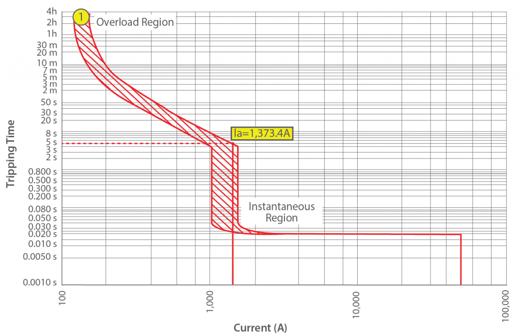
Figure 3: Time-current curve of a 160A breaker from PowerCAD® software
Achieving circuit breaker discrimination
Each circuit breaker contains a range of different settings that can be used to vary the time-current curve of the device, as well as allowing for a range of current and time values for the breaker to trip at. It is through these settings that the shape of the curve can be altered in order to successfully coordinate as per the AS/NZS 3000:2018 standards. There are multiple ‘shall’ (mandatory) requirements that need to be met and are mentioned in clause 2.5.7.2.3 based on the type and size of the protective devices.
Circuit Breakers
According to AS/NZS3000:2018, 2 circuit breakers (C) connected such that C2 is downstream and C1 is the upstream shall be selected:
- If the current rating of C2>= 800 A, discrimination shall be provided via a coordination study using manufacturer’s data.
- For a current rating range of 800 A > C2> 250 A, discrimination shall be provided between overload curves. Discrimination is deemed to be achieved if the minimum overload setting of C1>= 1.5 x the maximum overload setting of C2.
- If the current rating of C2 < 250 A, discrimination is deemed to be achieved if the minimum overload setting of C1>= 1.5 x the maximum overload setting of C2.
There are two main parameters that are used to achieve selectivity for circuit breakers.
- Pickup: The pickup of the device is the minimum current at which a trip is initiated within the protective device.
- Time delay: During the trip operation, time delay is introduced after the protection device senses the current has exceeded the pickup value.
To achieve successful selectivity, the trip time and current settings of a circuit breaker are generally manipulated until coordination is achieved with surrounding breaker curves. These settings are determined by the type of trip unit that is installed with the breaker and can either provide freedom in a wide variety of settings or be limited to certain values. Figures 4 and 5 below shows PowerCAD® screenshots displaying the range of settings that can be adjusted within trip units. Figure 4 shows a trip unit with six parameters that could be adjusted, where the trip unit displayed in Figure 5 has only one parameter that can be adjusted.
The Schneider Micrologic 5.3A contains a wide range of different settings for both current and time values, allowing for ease of discrimination when trying to coordinate the respective time-current curve. In contrast, Figure 5 contains the Schneider TM160D trip unit that only has the ability to change the tripping current of the device, meaning it is more difficult to coordinate with other devices.
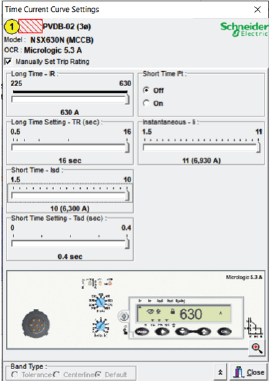
Figure 4: An example of a range of settings using the Schneider Micrologic 5.3A trip unit
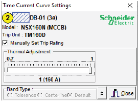
Figure 5: An example of limited settings using the Schneider TM160D trip unit
If all requirements in AS/NZS 3000:2018 are met, then successful coordination has been established. An example of correct circuit breaker discrimination is shown below in Figure 6. The red curve is a 630A circuit breaker located in the main switchboard. The blue curve is a 160A circuit breaker located in the solar distribution board and is an example of perfect selectivity between protective devices.
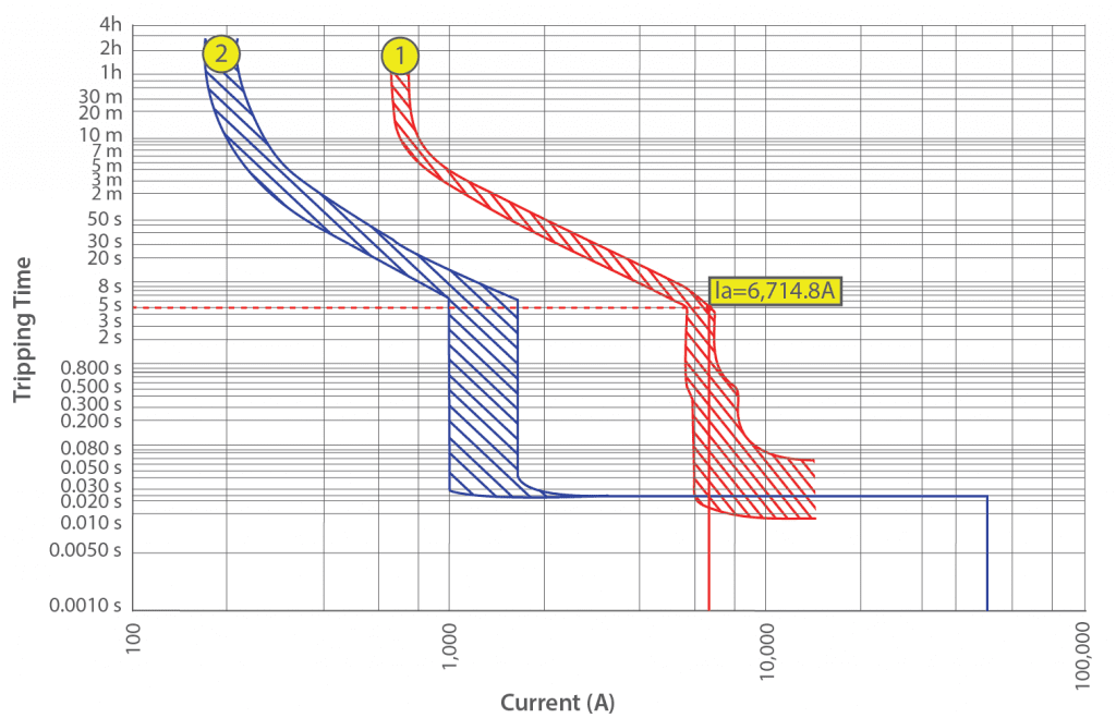
Figure 6: Example of successful protective device discrimination
In contrast, Figures 7 and 8 demonstrate two examples of miscoordination between circuit breakers, using the same devices as in Figure 6. Whilst each trip unit remained the same, the trip settings were adjusted for both devices for each scenario. Figure 7 produces an error with device discrimination in the PowerCAD® software as the two curves overlap one another. This causes potential for nuisance tripping, with the event of the upstream 630A breaker tripping before the 160A blue curve likely to occur. Likewise, Figure 8 does not contain proper device selectivity as it defies clause 2.5.7.2.3(a)(iii) where the minimum rating of the upstream breaker (red curve) must be rated 1.5 times the maximum rating of the downstream breaker (blue curve) in the instantaneous region.
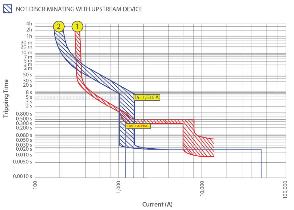
Figure 7: An example of miscoordination due to overlapping curves, as demonstrated by PowerCAD®
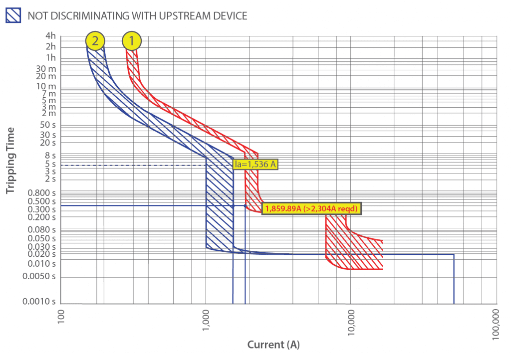
Figure 8: An example of miscoordination due to a clause in AS/NZS 3000:2018 not met, as demonstrated by PowerCAD®
Conclusion
With network applications becoming increasingly strict across the board, protective device coordination studies are becoming more prevalent prior to connecting a PV system to the grid. Protection coordination is equally important for ensuring the safety of the system operator and system components. It is therefore important that when designing, these studies are carried out prior to installation and final designs, as it is a costly and complex procedure to replace circuit breakers once the system has been energised.
GSES provides design and consultancy services which includes the application to connect with various DNSPs throughout Australia. GSES offers services such as protection coordination studies, detailed three-phase and single-phase fault analysis and earth fault studies. For more details contact our design team at design@mindaro.energy.