As Australia continues to see the trend to increase system capacity to medium or large scale Grid-connected PV system, it becomes valuable for Inverter Energy Systems (IES) to have ways to support the power quality of the grid. The most recent revision of the Australian Standard AS/NZS 4777.2: Grid connection of energy systems via inverters Part 2: Inverter requirements reflects
this sentiment.
AS4777.2 introduced inverter functions which controls the way inverter produces reactive power to demand, known as the fixed power factor mode and reactive power mode, and outlines their required operational behaviour. Local distributed network service providers (DNSPs) may require these functions to be enabled. For a refresher on what power factor is, take a look at the previous GSES article Power Factor and Grid-Connected Photovoltaics System.
A factor to consider when these modes are enabled is their effect on the voltage rise calculations; while leading power factors will reduce voltage rise compared to a power factor of unity, a lagging power factor will increase the voltage rise, and may result in the system requiring bigger cables ensure that the expected voltage rise of the system falls within the voltage rise requirements outlined by AS/NZS 4777.1:2016 Grid connection of energy systems via inverters Part 1: Installation requirements.
This article highlights the power factor modes requirements and voltage rise requirements, explains how voltage drop calculations is affected by enabling power factors, and demonstrates methods for carrying out the voltage rise calculations for different power factors as per AS/NZS 3008.1.1 :2017 Electrical installations—Selection of cables.
Fixed Power Factor & Reactive Power Modes (AS/NZS 4777.2:2015)
AS/NZS 4777.2 :2015 Clause 6.3.3 prescribes the behaviour of the two inverter response modes which allows inverter to output reactive power. These are the Fixed Power Factor mode and Reactive Power mode. While these functions are disabled by default, the local distributed network service provider (DNSP) may require them to be enabled as part of connection conditions.
Fixed Power factor mode
If this mode is enabled, then the inverter will be required to operate between the range of 0.8 leading to 0.8 lagging and no lesser. When the inverter power output changes, the inverter will vary the reactive power output to ensure that the target power factor is met.
Reactive Power mode
If this mode is enabled in an inverter, then the maximum ratio of the reactive power (Vars) to the rated apparent power (VA) should be 100%. The electrical distributor can fix the reactive power at a constant value depending on the grid requirement. This means that the power factor may fall below 0.8 leading/lagging to supply a fixed amount of reactive power.
Voltage rise requirement (AS/NZS 4777.1:2016)
AS/NZS 4777.1:2016 specifies that the overall voltage rise from the point of supply to the inverter AC terminal to be 2% or less of the nominal voltage at the point of supply.
Figure 1 below illustrates how the 2% voltage rise allowance is a combination of voltage rise between the point of supply and the main switchboard (Consumer mains) and voltage rise between the main switchboard and the inverter AC terminal (Sub-mains).
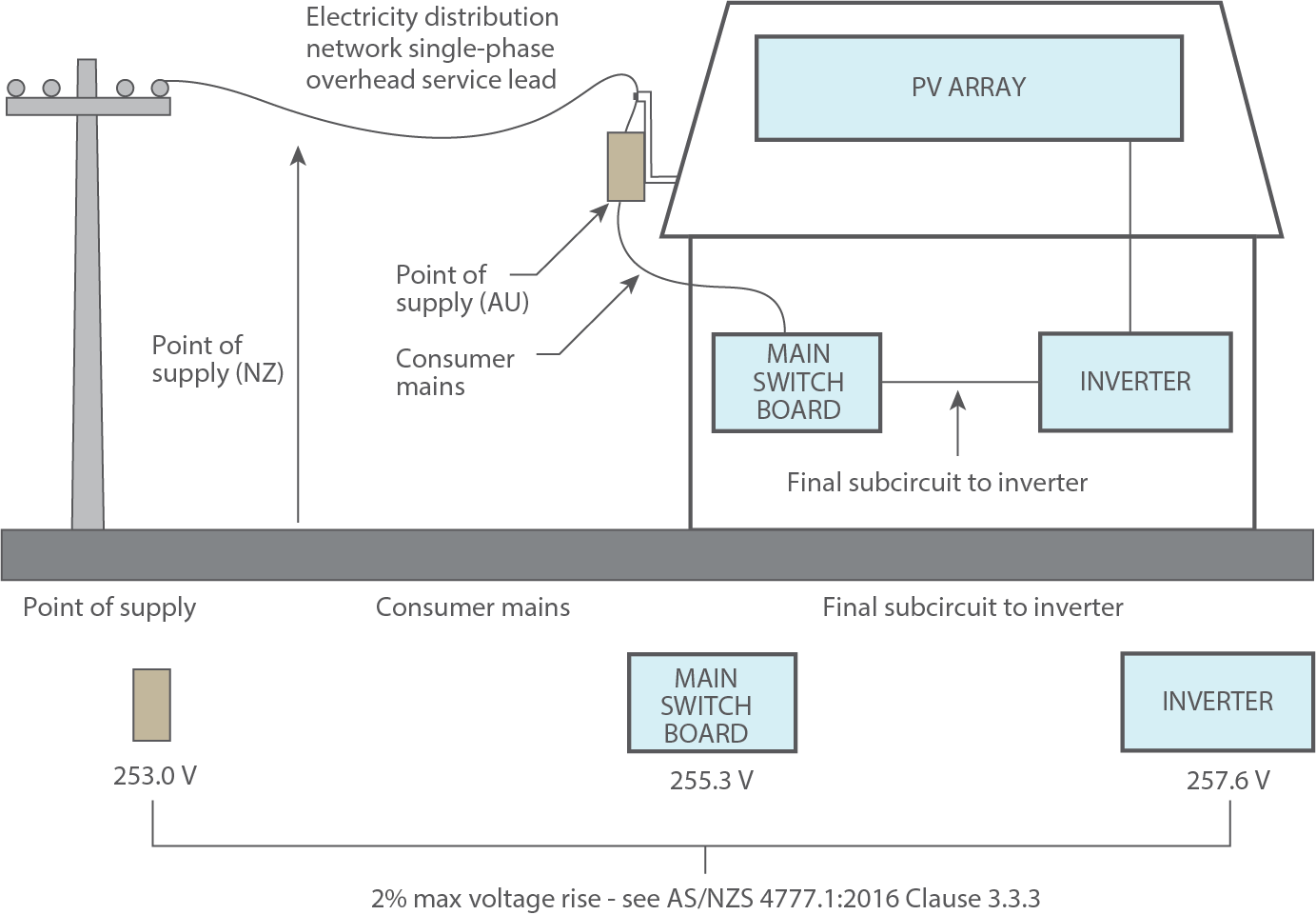
Figure 1: Figure C1 from AS/NZS 4777.1:2016 showing example of application of voltage rise for IESs.
This definition of voltage rise means that a larger cable can be used between the inverter and the main switchboard to reduce the overall voltage rise.
Calculating Voltage Rise Accounting for Power Factor (AS/NZS 3008.1.1:2017)
The voltage rise experienced at any one site is affected by the length of the route, the anticipated load current, the conductor voltage rise per unit of distance, and the power factor experienced at site.
The cable voltage rise per unit of distance is dependent on the conductor cross section area. AS/NZS 3008.1.1:2017 Selection of Cables provides equations for the calculation of voltage rise/drop across cables as well as pre-calculated voltage rise values, cable resistance values, and cable reactance values for different conductor cross section areas.
Note that while AS/NZS 3008.1.1:2017 refers to the calculations as voltage drop, mathematically voltage drop and voltage rise are the same thing.
Unity Power Factor
For unity power factor operation, the formula for calculating voltage rise is given as follows:
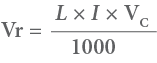
Where:
- Vr = Voltage rise
- L = Route length
- I = Rated Current of the inverter
- Vc = Voltage rise of the cable.
AS/NZS 3008.1.1 Tables 40 to 51 provides pre-calculated Vc values for various conductor cross section areas.
Non-unity Power Factor
For non-unity power factor operation, the calculation of the voltage rise becomes a bit more complex. The two vector diagrams below illustrate how the supply voltage, Vs, can be affected by lagging and leading power factor.
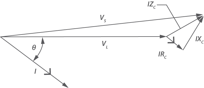
Figure 2: Vector diagram with Cos Θ = 0.8 lagging
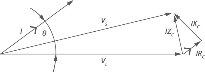
Figure 3: Vector diagram with Cos Θ = 0.8 leading
Where:
- I = Current flowing in cable
- VS = Voltage at supply
- VL = Voltage at load
- IRC = cable resistance multiplied by current
- IXC = cable reactance multiplied by current
- IZC = voltage drop associated with impedance of the cable
- θ = phase angle corresponding to the power factor experienced
The voltage rise is the difference in length between VS and VL.
The equations for calculating three phase voltage rise given the power factor are:
Equation 2
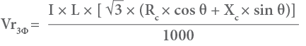
Equation 3

Where:
- L = route length of circuit, in metres
- Rc = cable resistance, in ohms per metre
- Xc = cable reactance, in ohms per metre
- θ = phase angle corresponding to the power factor experienced
Values of Rc and Xc are given in units of ohms per kilometre (Ohms/km) in Tables 30 to 39 of
AS/NZS 3008.1.1
Worked example
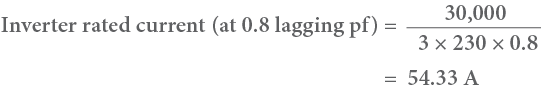
Consider the installation below: a 3 phase Grid-Connected inverter is installed on a commercial building. The sub-mains (with max output of 30kVA and nominal output of 30kW) run from the inverter AC terminal to the Main Switchboard is 60 metres and the consumer mains run from the Main Switchboard to the Point of Supply is 35 metres. The size of the installed sub-mains cable is 25 mm2 (PVC insulation) and the size of the existing consumer mains cable is 16 mm2 (PVC insulation).
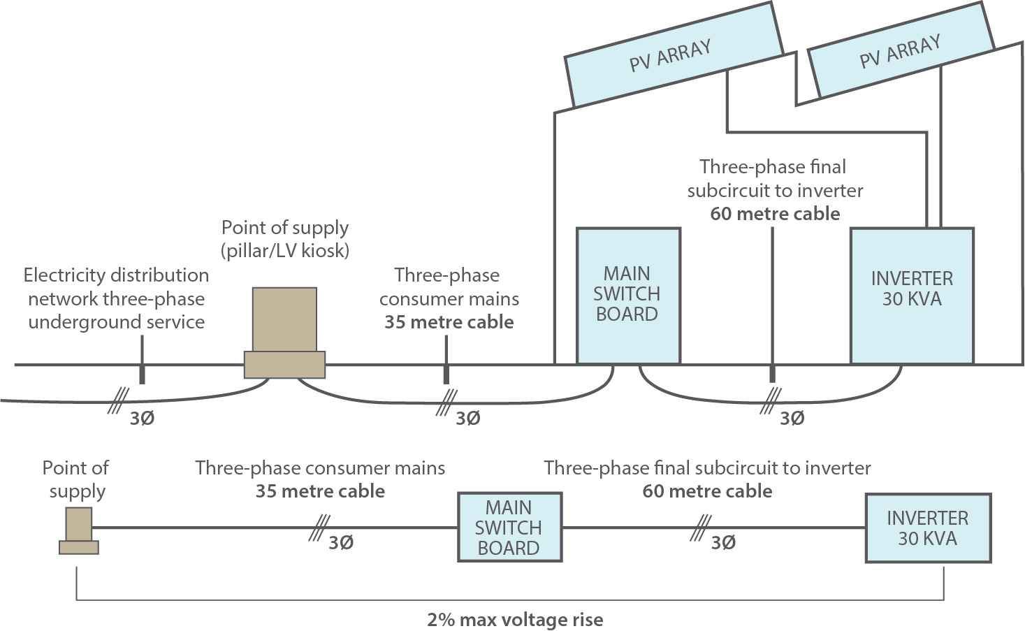
Figure 4: 30kVA Grid-Connected Installation
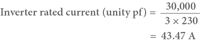
Case 1 – Unity power factor
The electrical distributor has asked for the inverter to operate at unity power factor
From AS/NZS 4777.1,
- Vr3ф= Vr3фsub-mains + Vr3ф consumer mains
- Vr3ф = 2% of 400V
= 8V
Using equation 1,
- Vr3ф sub-mains = 4.04 V (Vc = 1.55 mV/A.m for sub-mains from table 41 column 6)
- Vr3ф consumer mains = 3.69 V (Vc = 2.43 mV/A.m from table 41 column 6)
- Vr3ф = Vr3ф sub-mains + Vr3ф consumer mains
- Vr3ф= 4.04 + 3.69
- Vr3ф= 7.73 V
Since this value is below 8V, the selected cable size will be compliant with the 2% Voltage rise requirement.
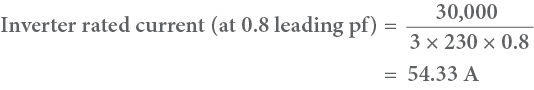
Case 2 – 0.8 Leading Power Factor
The electrical distributor has asked the site owner to set the inverter to 0.8 leading operation.
From AS/NZS 4777.1,
- Vr3ф= Vr3ф sub-mains + Vr3ф consumer mains
- Vr3ф = 2% of 400V
= 8V
Using equation 3,
- Vr3фsub-mains = 3.60 V (Rc = 0.884 ohm/Km from table 34 column 4; Xc = 0.116 ohm/Km from table 31 column 6)
- Vr3фConsumer mains = 3.45 V (Rc = 1.4 ohm/Km from table 34 column 4; Xc = 0.120 ohm/Km from table 31 column 6)
- Vr3ф = 3.60 + 3.45
- Vr3ф = 7.05 V
As this value is below 8V, the selected cable size will be compliant with the 2% Voltage rise requirement.
Case 3 – 0.8 Lagging Power Factor
The electrical distributor has asked the site owner to set the inverter to 0.8 lagging operation.
From AS/NZS 4777.1,
- Vr3ф = Vr3ф sub-mains + Vr3ф consumer mains
- Vr3ф = 2% of 400V
= 8V
Using equation 2,
- Vr3ф sub-mains = 4.38 V (Rc = 0.884 ohm/Km from table 34 column 4; Xc = 0.116 ohm/Km from table 31 column 6)
- Vr3ф Consumer mains = 3.92 V (Rc = 1.4 ohm/Km from table 34 column 4; Xc = 0.120 ohm/Km from table 31 column 6)
- Vr3ф = 4.38 + 3.92
- Vr3ф= 8.3 V
As this value is above 8V, the selected cable size will not be compliant with the 2% Voltage rise requirement. This means that the cable size will need to be increased to keep the voltage rise value below 2%.
Conclusion
With the introduction of power factor mode and fixed factor mode in AS/NZS 4777.2:2015, inverters may be asked to operate at varying power factors. As power factor affects voltage rise calculations, additional caution needs to be taken to ensure the 2% voltage rise requirement specified by AS/NZS 4777.1:2016 is met.
As shown in the worked examples, while leading power factors can reduce the voltage rise experienced at a site, a lagging power factor will increase the voltage rise. This means that a larger cable may need to be sized if it is anticipated that the inverter will be operating with a lagging
power factor.