
Photovoltaic technology has been making steady improvements since the first major silicon cell created by Bell Labs in 1954. As research and development continue to push solar cell technology forward (Figure 1), we often see a lag in the adoption of these advancements in commercial applications. Today, high efficiency solar cells that were once only seen in labs are installed on a global scale.
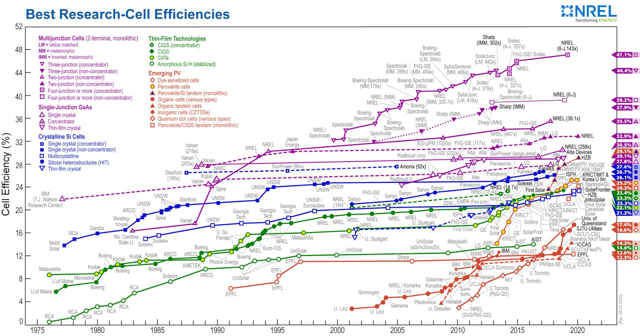
Figure 1: Efficiency improvements in research-grade solar cells since 1976
Source: NREL
Commercial adoption typically occurs when these innovations have proven to be scalable in the manufacturing process as well as being reliable on-site. Case in point, the Passivated Emitter and Rear Cell (PERC) solar cell, developed in Australia in the 1980s helped to establish a baseline efficiency of 20%. However, it has only been established as the most competitive crystalline-silicon technology in use as of 2015, with sales exceeding US $10 billion in 2017 and predicted to exceed US $1 Trillion by 2040. PERC cells have become the standard technology type amongst many module manufacturers such as Jinko, Yingli, and Trina, superseding older cell structures such as aluminium Back Surface Field (Al-BSF).
Half cut cells are another advancement in solar technology which has recently penetrated commercial solar applications and are rapidly becoming standard. While not as industry-shaking as the development of PERC cells, the uses and benefits of half cut cells have been a lot more immediately apparent in a commercial sense. This has led to a faster adoption rate in the industry, with 120 and 144 cell modules becoming increasingly common.
Higher efficiency cells can provide multiple performance and financial benefits. They can help to reduce balance of system costs, increasing the energy density per square metre of solar installations, and to work around the potential size and shading limitations of a site.
PERC Solar Cells
As with many solar cell technology developments, the principles behind PERC technology are based on the chemical structure of the photovoltaic materials at the micro level. This article presents a simplified explanation of PERC functionality for solar power system designers and installers.
What is PERC?
Passivated Emitter and Rear Cell (PERC) is a high efficiency solar cell architecture that differs from other conventional types of monocrystalline solar cells, such as aluminium back surface field (Al-BSF), as seen in Figure 2. In the Al-BSF structure, the metal on the rear of the cell is in direct contact with the silicon substrate. This full area metal/silicon interface causes a lot of losses, which limits the potential efficiency for this design.
In PERC cells, a very thin passivation layer is introduced between the base silicon wafer and the metal contact on the rear surface, with holes in the layer allowing for small areas of direct metal contact with the wafer.
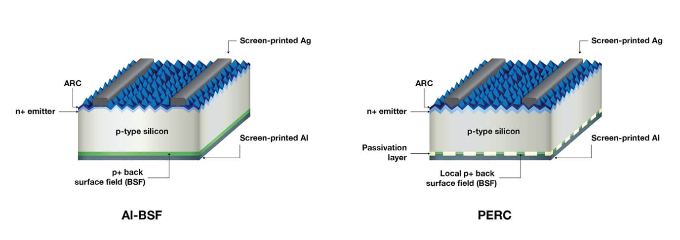
Figure 2: Solar cell structure in conventional AI-BSF cells compared to PERC cells
PERC cells provide an edge in efficiency in three main ways:
Reducing recombination losses
As light hits the cell, it excites electron-hole pairs, which creates a movement of electrons and thus current. However, at the surface of the silicon, where the crystal structure abruptly stops, there is a large concentration of defects that can trap the electrons, which limits the power output of the cell. In the Al-BSF design, the rear surface is completely covered by metal and so the density of traps on the rear surface remains high. The thin passivation layer on the rear surface in the PERC helps to significantly reduce the number of defects at the rear surface, which means that fewer electrons are lost. Avoiding these losses means that PERC solar cells can generate higher voltages.
Reducing optical losses
The thin dielectric layer at the back of the cell allows for any light that has passed through the silicon to the rear of the cell another opportunity to generate current. By reflecting the light off the back surface, this increases the overall percentage of light that can potentially be absorbed by the cell for current generation, which, in turn, increases efficiency.
Reduced temperature coefficient
When solar cells operate at high temperatures on a rooftop or in the field, the efficiency can reduce, primarily due to a drop-in voltage at elevated temperature. Due to the improved carrier collection efficiency in PERC solar cells compared to Al-BSF, they perform better at high temperatures. Additionally, the lack of metal on the back-surface means that PERC cells absorb less infrared light, which can help to reduce heating.
PERC considerations
With the increase in efficiency that PERC technology provides, there are also a few issues to be wary of.
LID
Light induced degradation is an unavoidable form of degradation that a solar module can experience within its first few days in the sun. It is a well-documented issue that leads to an initial power loss in the first year of a module’s life – usually taken into account in a module manufacturer’s warranty.
PID
Potential induced degradation is a phenomenon which occurs as a result of leakage current moving from the glass plate, through the encapsulating material and anti-reflective coating (ARC) to the cell. This is the result of a negative potential in the system components with respect to earth, leading to exponential performance losses in some cells.
In terms of manufacturing considerations, material selection for the glass, encapsulating material and ARC can be factored in to help mitigate the effects of PID. Earthing the negative leg of a system can also prevent the occurrence of PID, however most solar power systems use transformerless inverters and thus cannot be functionally earthed.
LeTID
Light and elevated temperature induced degradation has a more profound effect in terms of panel degradation. Between LID and LeTID, the latter is less understood. Some PERC modules were documented in 2016 to have exhibited a module power degradation that exceeds 10% over 3 years of testing.
While these are potential areas of concern, there has been a significant amount of research and development invested to help minimise these degradation issues. In February 2020, researchers at UNSW unveiled new technology with the claim that it can help to reduce both LID and LeTID.
Benefits of using PERC technology
The obvious benefit that comes with higher efficiency solar cells such as PERC is that it can help at sites where the available area is limited – allowing for more energy-dense installations.
By reducing the number of modules needed to achieve any given capacity, overall system costs can potentially decrease. This ties directly to balance of system costs (BOS) such as racking and wiring, and can help reduce installation time.
Half Cut Solar Cells
Another innovation to solar cell technology is half cut cells. REC introduced the first commercial half cut cell in 2014. Since then, these types of solar cells have been rapidly adopted by the industry due to their ability to increase the power output of a solar system with minimal alterations needed in the manufacturing process.
Half cut cell modules are made of cells that have been cut in half, resulting in a total of 120 or 144 cells in a single module – doubling the total count in comparison to a traditional solar module. Each half-cut cell produces the same voltage as a standard cell but only half the current, thus they are arranged in parallel strings (Figure 3) to mimic the voltage and current ratings of a conventional module. There are many benefits to this type of cell, many of which use PERC technology. The most prominent benefit is the reduction in current per individual cell, lowering resistive losses, which results in a gain in power per square metre.
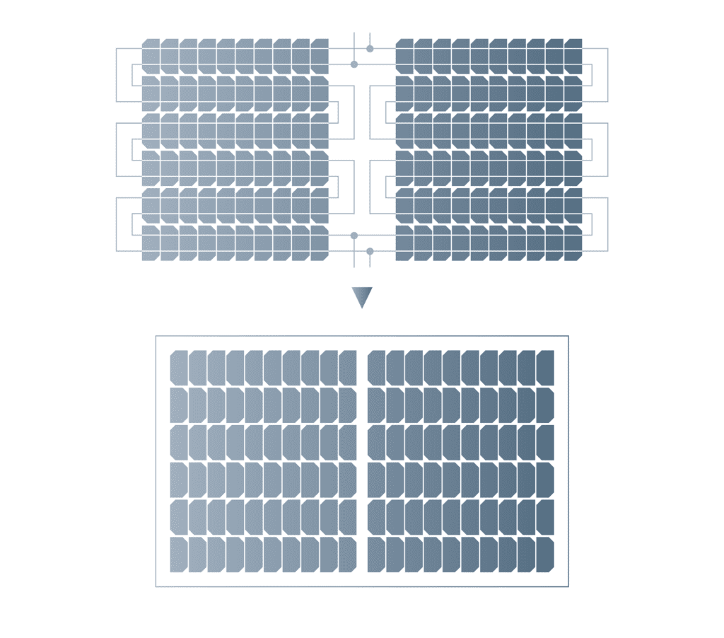 Figure 3: Arrangement of cells in a half cut cell module
The manufacturing process to create half cut cells does include a few additional steps – cutting, either by laser or a wire saw, and increasing the complexity of the stringing of the cells. Automation of both of these processes has helped manufacturers to overcome this barrier, reducing the chance of error and associated costs. This has resulted in a high level of adoption amongst many of the large manufacturers of solar modules, with half cut technology capturing an increasing market share across the world. Jinko Solar is one of the manufacturers that are transitioning their processes towards a majority focus on half cell production – with a predicted output of 20 GW of production in 2021, of which 16 GW will be comprised of half cut cells.
Half cut cell modules have three main benefits over conventional modules:
Reduced resistive losses
Halving the cell size splits the total current between the two halves. This plays a vital role in a half cut cell’s ability to reduce resistive losses, comprising of a cell’s series resistance and the series resistance of the connecting ribbons. Due to the quadratic relationship between current and power, where P = I2 x R, the current is halved compared to a full cell, so the power loss is ¼ of that in a full cell. Therefore when there are two strings of half cut cells the resistive power loss is ½ of that of a full cell module and helps to increase overall module performance.
Better performance in shaded conditions
Half cut cell technology has the potential to perform better than full cell modules when experiencing certain shading conditions. This can be attributed to the required stringing configuration as a result of the doubling of cells per module.
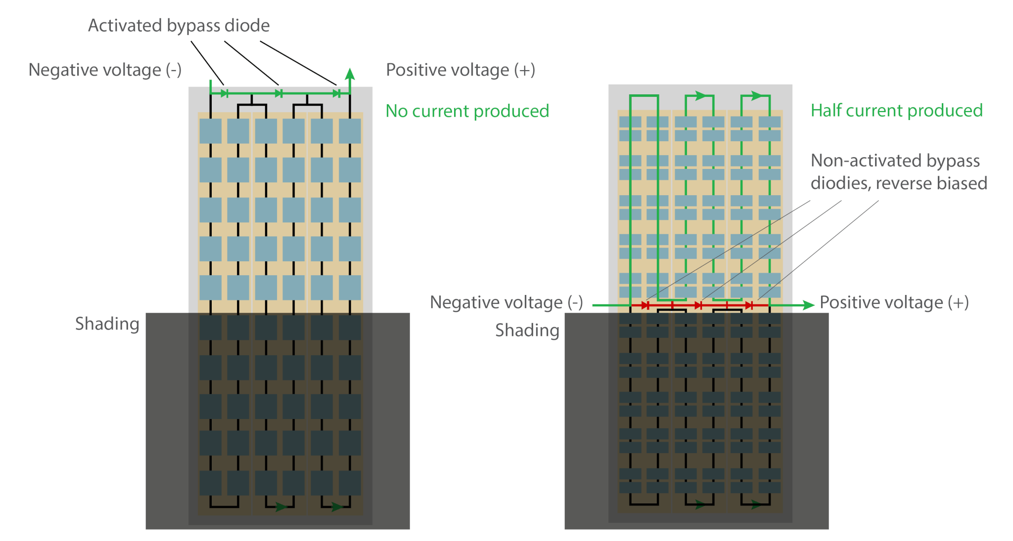
Figure 4: An example of “portrait” shading where a half-cut cell module outperforms a conventional module
As seen in Figure 4, half-cut cells are strung in series and connected to a bypass diode, similar to the configuration of a full cell module. The difference is that each bypass diode is paralleled with two strings of cells. When the module experiences partial shading across one half of the module, the other half of the module is able to continue producing power and the bypass diodes remain inactive. This allows for increased flexibility in module arrangement at sites that experience shading.
Reduced hot spot impacts
When a module is partially shaded, hot spotting can occur as power is dissipated in the shaded cells. This can result in overheating of the shaded cells. Modules that utilise half cut cells produce less current than that of a full cell, and this, in turn, helps to reduce the amount of dissipated power in the shaded cells – mitigating hotspot degradation.
Half cut considerations
Increased complexity
Due to the increased number of cells, there are more points of potential failure within the module – from the cells themselves or the string connections and solder points. Automation of the module manufacturing process has helped to mitigate these complexities.
Installation considerations
Traditional solar modules have junction boxes that are located at one end of the back of the module. In contrast, half cut cell modules have two junction boxes, a positive and negative terminal, that are located in the middle of the module. While the cables are typically long enough to connect the modules in either portrait or landscape, there are associated orientation considerations for installers when using these types of modules.
Benefits of using half cut technology
Half cut cell modules have proven to have higher power outputs per square metre than their full cell counterparts. Similar to the comparison of PERC and Al-BSF cells, half cut cells can potentially improve the payback time and Levelised Cost Of Electricity of a system that chooses to utilise this type of solar cell technology.
Half cut cells also have the additional benefit of being adaptive at sites where shading is unavoidable. Half cut cell modules oriented so that they experience “portrait shading” will see less power loss in comparison to similarly positioned modules that use traditional full cells.
Further Resources:
Development of the PERC Solar Cell
Potential Induced Degradation – GSES
Influence of Al2O3 and SiNx passivation layers on LeTID
Half-cell module behaviour and its impact on the yield of a PV Plant