
Our recent technical article on AS/NZS 3008.1.1:2025 Updates for Solar Cable Design outlined the key changes introduced in the updated standard which included dedicated DC cable tables, revised HF-110 values, and the terminology shift from “derating factor” to “correction factor.” For solar designers and installers, understanding how to apply cable sizing correction factors under the new standard is just as important as knowing what has changed.
With a new version of AS/NZS 3008.1.1 out, we thought we would revisit cable sizing and correction factors for a typical rooftop PV system. In summary: if the short circuit current of your PV module does not exceed 15A and you are not paralleling strings, 4mm2 conductors meets this standard. But if you do parallel strings, then you will need to upsize to 6mm2.
By the end of this example, you will have a clear picture of when a 4mm² DC conductor is sufficient under the 2025 standard, and when project conditions demand an upsize to 6mm².
System Configuration
For this example, we will consider a typical 10kW inverter PV installation with the following parameters:
- DC array capacity: 13.2kW (30 x 440W modules)
- String configuration: 2 strings of 15 modules
- Cable type: 4mm² DC twin XLPE
- Installation method: Enclosed in HD conduit within the roof cavity
Current-Carrying Capacity (CCC)
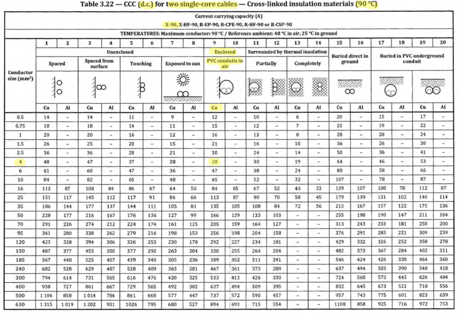
Under AS/NZS 3008.1.1:2025, 4mm2 DC Twin XLPE will use Table 3.22 (new DC table!) for Current Carrying Capacity. This is one of the most significant practical changes in the 2025 edition.
DC twin cable is considered 2 single core conductors since each conductor’s insulation is separate and not in an overall sheath.
For this installation, the worst-case scenario is the cable run within the roof cavity, enclosed in PVC conduit in air. Although exposure to sun yields a lower CCC from the table alone, the enclosed conduit scenario is used here, as it represents the more conservative design condition for Australian rooftop solar installations when correction factors are considered.
From Table 3.22, Column 9: CCC of 4mm² XLPE cable = 38A
Temperature Correction Factor
Roof cavities in Australian climates can reach ambient temperatures of up to 70°C during summer. This significantly exceeds the 40°C reference ambient temperature assumed in the standard’s base CCC tables. Thus, a temperature correction factor (CF) must be applied.
This is where the updated terminology introduced in AS/NZS 3008.1.1:2025 becomes relevant in practice. What was previously called a “derating factor” is now formally referred to as a Correction Factor (CF). The calculation method remains the same, but designers should ensure their documentation and design tools reflect the updated language.
For conductors enclosed in air, the applicable table is Table 3.44.
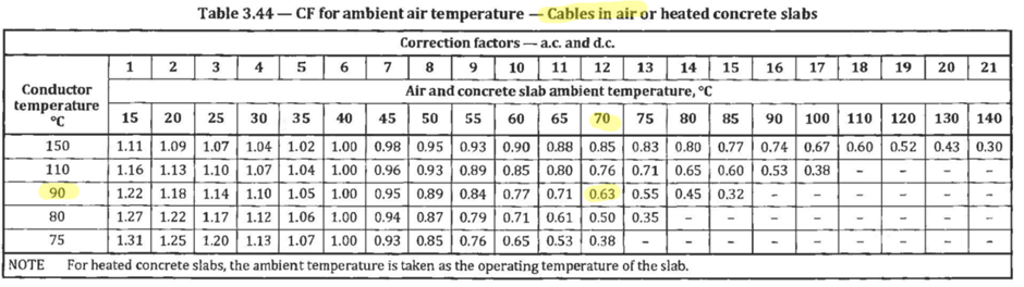
Inputs:
- Ambient temperature: 70°C
- Conductor operating temperature (XLPE): 90°C
From Table 3.44: Temperature CF = 0.63
Bunching Correction Factor
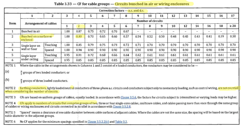
With 2 strings routed through the same conduit, a bunching correction factor must also be applied. Heat dissipation is reduced when multiple cables share an enclosure, which lowers the effective current-carrying capacity of each conductor. Note, that the earth conductor is excluded from the circuit count per the standard’s requirements.
For cables enclosed in air or within wiring enclosures, the applicable table is Table 3.33, using Item 2 (Bunched on a surface or enclosed) with N = 2 circuits.
From Table 3.33: Bunching CF = 0.80
Adjusted CCC
Applying both correction factors to the base CCC value from Step 1:
38A × 0.63 × 0.80 = 19.15A adjusted CCC
This means that before accounting for any module-level requirements, the effective current-carrying capacity of the 4mm² conductor in this installation has already been reduced by approximately 50% of its rated value which is a direct consequence of the real-world installation conditions.
Accounting for AS/NZS 5033 – Maximum String Current
Cable sizing for solar DC circuits does not conclude with AS/NZS 3008.1.1 alone. The AS/NZS 5033:2021 PV array installation standard introduces an additional requirement through the maximum string current (Istringmax), which accounts for the constant-current behaviour and resistance build-up inherent in PV string cables under operating conditions. It also considers that irradiance can at times be greater than 1000 W/m2.
Per AS/NZS 5033 Clause 3.3.3.1, the allowable module short-circuit current is determined by dividing the adjusted CCC by the Istringmax factor of 1.25:
Allowable Isc_mod = 19.15 ÷ 1.25 = 15.32A
The combined effect of temperature correction, bunching correction, and the AS/NZS 5033 string current factor reduces the effective current-carrying capacity of the 4mm² conductor to approximately 40% of its base rated value. This underscores why applying correction factors carefully, and cross-referencing between AS/NZS 3008.1.1:2025 and AS/NZS 5033:2021, is critical to safe and compliant solar cable design in Australia.
For complex installations involving underground cables, multi-core configurations, or tiered trenching, our article on specialised cable sizing using AS/NZS 3008.1.1 and IEC 60287 explores where international calculation methods may be more appropriate.
Conclusion and Design Implications
For a standard single-string rooftop PV configuration where the module short-circuit current does not exceed 15A, a 4mm² conductor remains compliant under AS/NZS 3008.1.1:2025.
However, designers should carefully assess the following scenarios, where upsizing to 6mm² will likely be required:
- Paralleling strings: Combining strings increases fault current exposure, quickly pushing designs beyond the 15.32A threshold established in this example
- Bifacial modules: The additional irradiation captured by bifacial modules can elevate short-circuit currents beyond standard single-face ratings
- High ambient temperature installations: Roof cavities in hotter climates or poorly ventilated spaces may require more conservative correction factors than those applied here
As modern solar modules trend toward higher short-circuit currents, designers are encouraged to verify correction factors on a per-project basis under the updated AS/NZS 3008 2025 standard, rather than assuming that 4mm² will universally suffice across all rooftop solar installations in Australia.
With the mandatory implementation date of 19 June 2026 approaching, now is the time to familiarise yourself with the updated tables, correction factor methodology, and cross-standard requirements that govern DC solar cable sizing under the new standard.
A CPD course covering the practical implications of AS/NZS 3008.1.1:2025 is currently in development. In the meantime, get in touch with the GSES team if you have questions about solar cable sizing compliance or design support.