GSES communicates factual, up-to-date and evidence-based information for publication. This includes information on the issues surrounding DC circuit breakers, earthing fundamentals, how to sell solar, and information on isolator enclosures.
Voltage Drop Cable Sizing Solar PV & Battery Systems
Posted on by Sandesh Gudi
How voltage drop cable sizing works for solar and battery systems
Voltage drop cable sizing for solar PV and battery systems is one of the most consequential parts of system design yet it’s also one of the most frequently misunderstood. If a cable is inappropriately sized, best case scenario it is an overpriced commodity. However, if the cable conductor is not sized correctly to handle current flowing through it and heats up, it could burn the insulation around it and start a fire. Therefore, selecting an optimal cable size is quite important.
When you are sizing a cable, the parameters you should consider are voltage drop, operational current, and fault current. In this article we will deep dive into one of the parameters – voltage drop/rise, and see how it affects cable sizing. Specifically we are trying to make things easier for you, and identify at which cable lengths you can reasonably ignore voltage drop and when you must pay attention. What we will show in the article is PV cables <40m, Battery cables < 10m, Single phase inverter cables < 5m, and three phase inverter cables <15m can reasonably ignore voltage drop as operational current will take precedence.
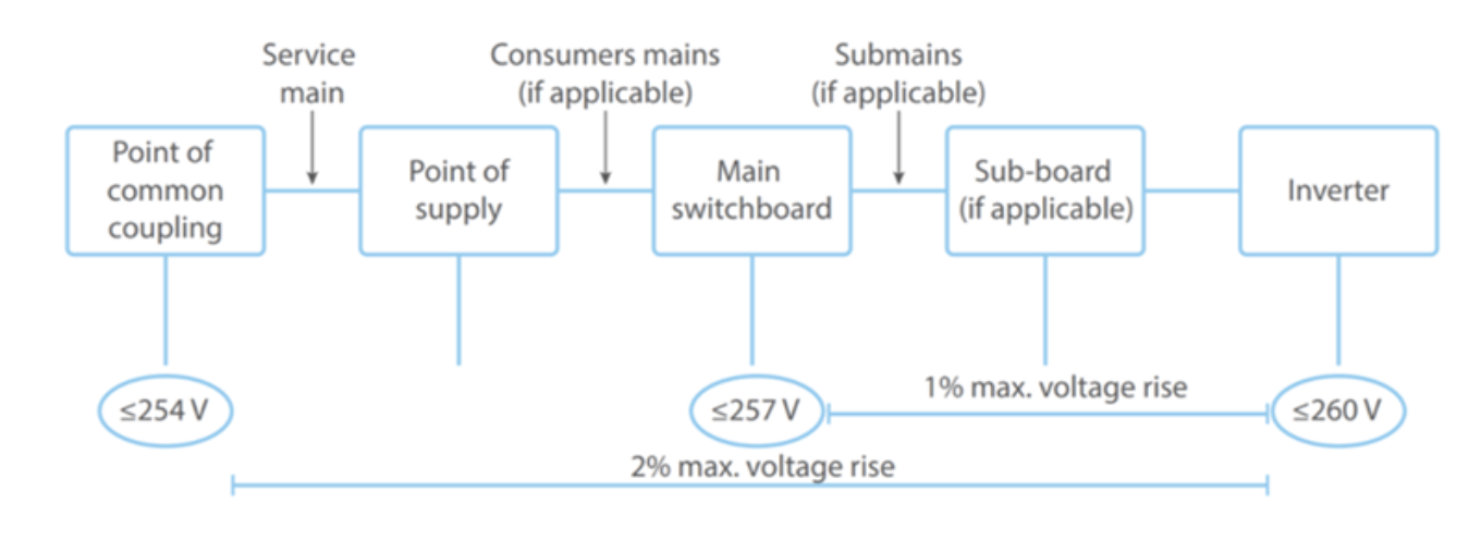
Looking at voltage in cable sizing, we will encounter two terms quite often – voltage drop and voltage rise. Voltage drop is performance loss due to the cable’s internal resistance, while voltage rise is the increase in voltage from the MSB to the inverter to allow for export of energy to the grid. The limits on permitted voltage rise and drop are governed by AS/NZS 4777.1:2024, which should be read alongside any applicable network provider requirements. This should be complied with, alongside any network provider limits. Under AS/NZS 5033:2021, a recommended 3% voltage drop is permitted on the DC side between the PV array or DC battery and the inverter. On the AC side between the point of attachment to the grid and the Inverter, a 2% voltage rise limit is permitted which includes a 1% rise from the MSB to the inverter.
Figure 1: Permitted voltage rise between the inverter and point of attachment to the grid (Source: GSES)
The voltage drop/rise in a cable is determined by:
Conductor area
Length of the conductor
Current flow through the conductor
And the equation for calculating voltage drop/rise is:
VD = (L x I x VC) / 1000
Where:
VD = actual voltage drop (in V)
L = route length (in m), defined as the distance measured along a run of wiring from the origin of the circuit to the point of consideration
I = current flow (in A). For PV DC cables, the ISC current (at STC) should be used.
VC = millivolt drop per amp-metre route length (in mV/Am)
Repurposing the above equation, we can find the length constraint for each cable size and this will help us get a good idea of how long a cable you can lay for the most conservative cable size (in this case smaller cables) which will still meet the 3% voltage drop and 2% voltage rise limits.
We can rearrange the above voltage drop/rise equation as follows:
I = Assumptions based on the most conservative components in the market currently
For a detailed breakdown of what changed in this standard and how it affects solar cable design, see our AS/NZS 3008.1.1:2025 guide.
PV System DC cables
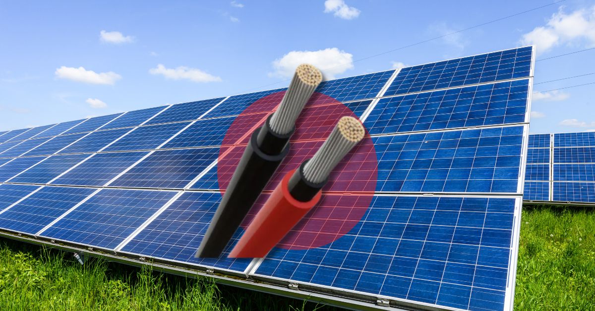
Figure 2: PV System Cables
For voltage drop cable sizing in solar PV systems, a commonly used cable is a Copper (Cu) conductor with XLPE insulation and cable size of 4mm2 (unless your PV strings are paralleled). Let’s assume a single string for this as it is much more common, and a conservatively high short-circuit current (I) value of 15A.
We need to consider one final assumption for the equation – voltage of the PV string. Here, again we go for the more conservative value (in this case leading to a lower system voltage). Say the VMP value of the PV Module is 32V and there are 8 of them connected together in series. In that case the length of the cable would be as follows:
Input:
VMP = 32V
No. of modules = 8
I = 15A
Loss% = 3%
Cable size = 4mm2
Output:
VD = Loss% x System Voltage
VD = Loss% x Vmp x No. of modules
VD = 0.03 x 32 x 8 = 7.68 V
VC = 11.8 (for 4mm2 cable as per Table 4.16 of AS/NZS 3008.1.1:2025)
L = (VD x 1000) / (I x VC)
L = (7.68 x 1000) / (15 x 11.8)
L = 43.39m ~ 43m
Based on the above calculations, any cable length of less than 43m meets the voltage drop requirements for the PV DC cables of sizes greater than 4mm2. If it exceeds this length, you should look at voltage drop calculations to find the optimal cable size.
Now, let’s look at another set of DC cables. We’ll look at DC battery systems or Section 5 Batteries (Pre-assembled battery systems) as per AS/NZS 5139:2019.
Continuing with the most conservative approach, we will look at the maximum cable length for a system composed of 2 stacked battery modules with a nominal battery voltage of 128V and operating current value of 30A. Based on the battery operating current we need a 32A Circuit Breaker (CB). The cable size needs to have Current Carrying Capacity (CCC) which is greater than this value. Assuming the cable is a Copper (Cu) conductor with XLPE insulation and looking at Table 3.22 of AS/NZS 3008.1.1:2025 we get a cable size of 4mm2. Now let’s take a look at the maximum length allowed for a 3% voltage drop in the cables:
Input:
Nominal Voltage = 128V
I = 30A
Loss% = 3%
Cable size = 4mm2
Output:
VD= Loss% x System Voltage
VD = 0.03 x 128 = 3.84 V
VC = 11.8 (for 4mm2 cable as per Table 4.16 of AS/NZS 3008.1.1:2025)
L = (VD x 1000) / (I x VC)
L = (3.84 x 1000) / (30 x 11.8)
L = 10.84m ~ 10m
Continuing the calculations with the above assumptions except for upsizing the cable size to 6mm2 (most conservative cable size currently), the length constraint now is:
Input:
Nominal Voltage = 128V
I = 30A
Loss% = 3%
Cable size = 6mm2
Output:
VD = Loss% x System Voltage
VD = 0.03 x 128 = 3.84 V
VC = 7.85 (for 6mm2 cable as per Table 4.16 of AS/NZS 3008.1.1:2025)
L = (VD x 1000) / (I x VC)
L = (3.84 x 1000) / (30 x 7.85)
L = 16.31m ~ 16m
The conclusion from the above is that, for battery DC cables with a cable size of 4mm2 a 10m length and for cable size 6mm2 a 16m length meets the 3% voltage drop limits. Any lengths exceeding this will require a higher cable size.
Finally, let’s do a deep dive into the AC cable size lengths based on the permitted 1% voltage rise allowed between the MSB and the inverter. We will take a look at both single and three-phase inverter system AC cables to the MSB for a range of sizes to determine the acceptable cable lengths.
This 1% allocation from the MSB to the inverter sits within the broader voltage rise framework explained in our AS/NZS 4777.1:2024 overview.
Single-phase Inverters (System Voltage = 230V)
L = (VD x 1000) / (I x VC) ; where VD = Loss% x System Voltage = 0.01 x 230
L = (0.01 x 230 x 1000) / (I x VC)
Current: I = (P / V) = P / 230
Cable size is based on CCC requirements (Table 3.16 of AS/NZS 3008.1.1:2025) which is calculated based on CB rating (based on current).
VC value is found using Table 4.17(B) of AS/NZS 3008.1.1:2025. A factor of 1.155 is multiplied to the value as the standard table 4.17 (B) only has three-phase VC values.
Power (kW)
Current (A)
Cable size (mm2)
VC
Length (m)
5
21.74
2.5
16.4 x 1.155
5.58 ~ 5
8
34.78
6
10.2 x 1.155
5.61 ~ 5
10
43.48
10
4.04 x 1.155
11.33 ~ 11
15
65.22
16
2.54 x 1.155
12.02 ~ 12
Table 1: Single-phase Inverter maximum cable lengths
Three-phase Inverters (System Voltage = 400V)
L = (VD x 1000) / (I x VC) ; where VD = Loss% x System Voltage = 0.01 x 400
L = (0.01 x 400 x 1000) / (I x VC)
Current: I = (P / V) = P / 400
Cable size is based on CCC requirements (Table 3.19 of AS/NZS 3008.1.1:2025) which is calculated based on CB rating (based on current).
VC value is found using Table 4.17(B) of AS/NZS 3008.1.1:2025.
Power (kW)
Current (A)
Cable size (mm2)
VC
Length (m)
10
25
4
10.2
15.69 ~ 15
15
37.5
10
4.04
26.4 ~ 26
20
50
16
2.54
31.5 ~ 31
Table 2: Three-phase Inverter maximum cable lengths
Conclusion from the above calculations leads to cable lengths maximum of 5m for a single-phase system and 15m for three-phase system.
Maximum Cable Length Summary
As one can see, cable sizing is quite nuanced and very important. But from the conservative estimates taken above, it is reasonable to assume that when below the thresholds identified in Table 3 you will not need to consider voltage drop in your cable sizing process. The table below summarises the voltage drop cable sizing thresholds for solar PV and battery systems at a glance.
Cable
Max. Cable Length
PV DC Cable
40 m
Battery DC Cable
10 m
Single-phase Inverter AC Cable
5 m
Three-phase Inverter AC Cable
15 m
Table 3: Maximum cable length summary
Cable sizing is one of the more technically demanding parts of solar and battery system design and getting it right requires more than just running the numbers. If you’re looking to build a solid foundation in compliant system design, GSES offers accreditation courses in Grid-Connected Solar PV Systems and Grid-Connected Battery Storage Systems, covering design principles, Australian standards, and everything in between. Enrol today and gain the accreditation to back your expertise.