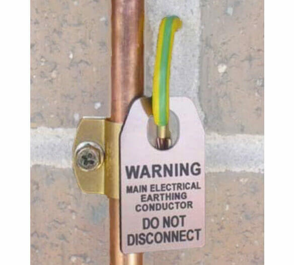
In an electrical network, an earthing system is a safety measure which protects human life and electrical equipment. As earthing systems differ from country to country, it is important to have a good understanding of the different types of earthing systems as the global PV installed capacity continues to increase. This article aims at exploring the different earthing systems as per the International Electrotechnical Commission (IEC) standard and their impact on the earthing system design for Grid-Connected PV systems. Note: The required anti corrosion paint is obscured by the tag in the featured picture; would you notice this?
Purpose of Earthing
Earthing systems provide safety functions by supplying the electrical installation with a low impedance path for any faults in the electrical network. Earthing also acts as a reference point for the electrical source and safety devices to correctly work.
Earthing of electrical equipment is typically achieved by inserting an electrode into a solid mass of earth and connecting this electrode to the equipment using a conductor. There are two assumptions that can be made about any earthing system:
- Earth potentials act as a static reference (i.e. zero volts) for connected systems. As such, any conductor which is connected to the earthing electrode will also possess that reference potential.
- Earthing conductors and the earth stake provide a low-resistance path to ground.
Protective Earthing
Protective earthing is the installation of earthing conductors arranged to reduce the likelihood of injury from electrical fault within the system. In the event of a fault, the non-current carrying metal parts of the system such as frames, fencing and enclosures etc. can achieve high voltage with respect to earth if they are not earthed. If a person makes contact with the equipment under such conditions, they will receive an electric shock.
If the metallic parts are connected to the protective earth, the fault current will flow through the earth conductor and be sensed by safety devices, which then safely isolate the circuit.
Protective earthing can be achieved by:
- Installing a protective earthing system where conductive parts are connected to the earthed neutral of the distribution system via conductors.
- Installing overcurrent or earth leakage current protective devices which operate to disconnect the affected part of the installation within specified time and touch voltage limits.
The protective earthing conductor should be able to carry the prospective fault current for a duration which is equal to or greater than the operating time of the associated protective device.

Functional Earthing
In functional earthing, any of the live parts of the equipment (either ‘+’ or ‘-‘) may be connected to the earthing system for the purpose of providing a reference point to enable correct operation. The conductors are not designed to withstand fault currents. In accordance with AS/NZS5033:2014, functional earthing is only permitted when there exists a simple separation between the DC and AC sides (i.e. a transformer) within the inverter.
Types of earthing configuration
Earthing configurations can be arranged differently at the supply and load side while achieving the same overall outcome. The international standard IEC 60364 (Electrical Installations for Buildings) identifies three families of earthing, defined using a two-letter identifier of the form ‘XY’. In the context of AC systems, ‘X’ defines the configuration of neutral and earth conductors on the supply side of the system (i.e. generator/transformer), and ‘Y’ defines the neutral/earth configuration on the system’s load side (i.e. the main switchboard and connected loads). ‘X’ and ‘Y’ can each take the following values:
- T – Earth (from French ‘Terre’)
- N – Neutral
- I – Isolated
And subsets of these configurations can be defined using the values:
- S – Separate
- C – Combined
Using these, the three earthing families defined in IEC 60364 are TN, where the electrical supply is earthed and the customer loads are earthed via neutral, TT, where the electrical supply and customer loads are separately earthed, and IT, where only the customer loads are earthed.
TN earthing system
A single point on the source side (usually the neutral reference point in a star-connected three-phase system) is directly connected to earth. Any electrical equipment connected to the system is earthed via the same connection point on the source side. These type of earthing systems require earth electrodes at regular intervals throughout the installation.
The TN family has three subsets, which vary by method of segregation/combination of earth and neutral conductors.
- TN-S: TN-S describes an arrangement where separate conductors for Protective Earth (PE) and Neutral are run to consumer loads from a site’s power supply (i.e. generator or transformer). The PE and N conductors are separated in nearly all parts of the system and are only connected together at the supply itself. This type of earthing is typically used for large consumers who have one or more HV/LV transformers dedicated to their installation, which are installed adjacent to or within the customer’s premises.
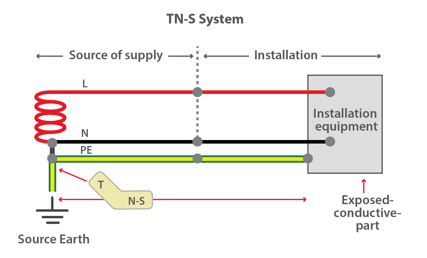
Figure 1 – TN-S System
- TN-C: TN-C describes an arrangement where a combined Protective Earth-Neutral (PEN) is connected to the earth at the source. This type of earthing is not commonly used in Australia due to the risks associated with fire in hazardous environments and due to the presence of harmonic currents making it unsuitable for electronic equipment. In addition, as per IEC 60364-4-41 – (Protection for safety- Protection against electric shock), an RCD cannot be used in a TN-C system.
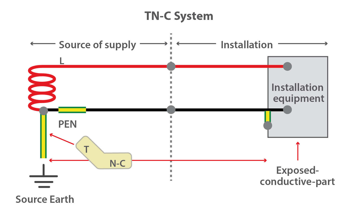
Figure 2 – TN-C System
- TN-C-S: TN-C-S denotes a setup where the supply side of the system uses a combined PEN conductor for earthing, and the load side of the system uses a separate conductor for PE and N. This type of earthing is used in distribution systems in both Australia and New Zealand and is frequently referred to as multiple earth-neutral (MEN). For a LV customer, a TN-C system is installed between the site transformer and the premises, (the neutral is earthed multiple times along this segment), and a TN-S system is used inside the property itself (from the Main Switchboard downstream). When considering the system as a whole, it is treated as TN-C-S.
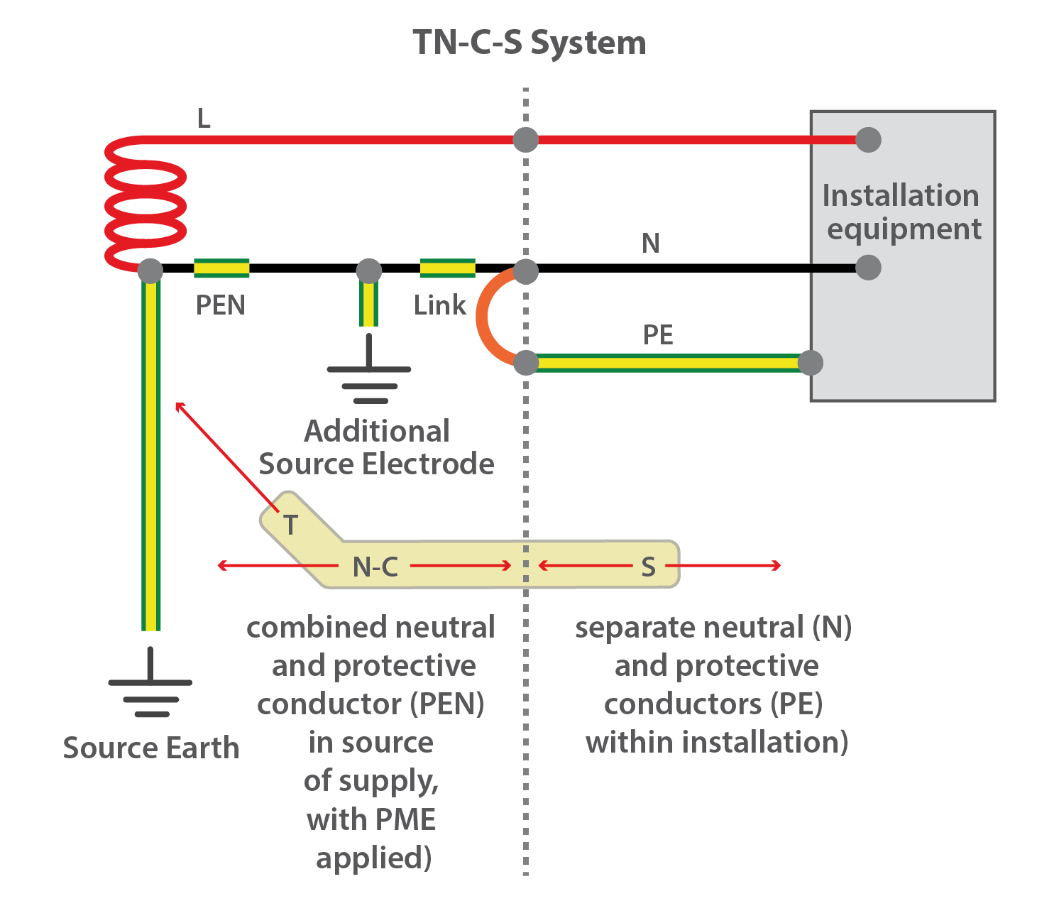
Figure 3 – TN-C-S System
In addition, as per IEC 60364-4-41 – (Protection for safety- Protection against electric shock), where an RCD is used in a TN-C-S system, a PEN conductor cannot be used on the load side. The connection of the protective conductor to the PEN conductor has to be made on the source side of the RCD.
TT earthing system
With a TT configuration, consumers employ their own earth connection within the premises, which is independent of any earth connection on the source side. This type of earthing is typically used in situations where a distribution network service provider (DNSP) cannot guarantee a low-voltage connection back to the power supply. TT earthing was common in Australia prior to 1980 and is still used in some parts of the country.
With the TT earthing systems, an RCD is needed on all AC power circuits for suitable protection.
As per IEC 60364-4-41, all the exposed conductive parts that are collectively protected by the same protective device shall be connected by the protective conductors to an earth electrode common to all those parts.
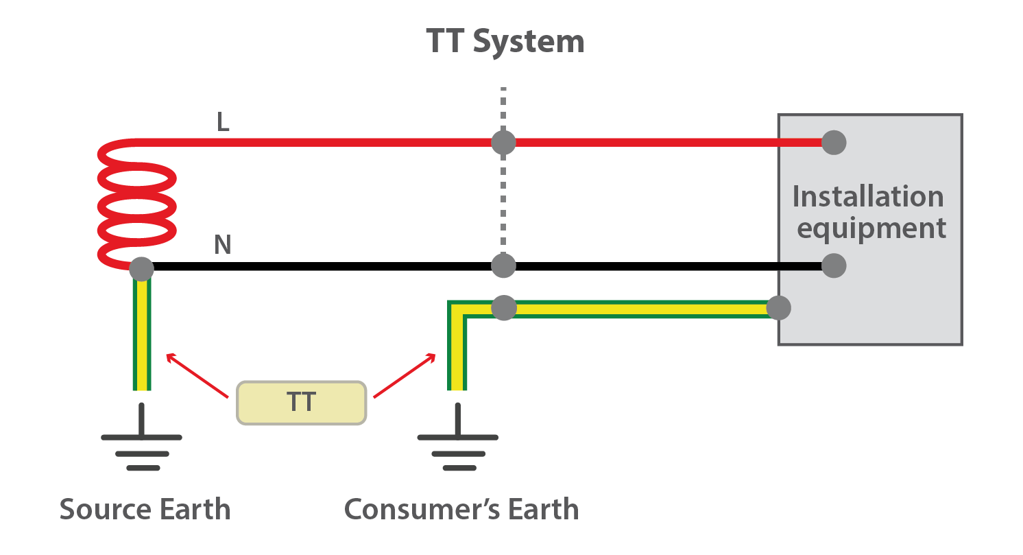
Figure 4 – TT System
IT earthing system
In an IT earthing arrangement, there is either no earthing at the supply, or it is done via a high impedance connection. This type of earthing is not used for distribution networks but is frequently used in substations and for independent generator-supplied systems. These systems are able to offer good continuity of supply during operation.
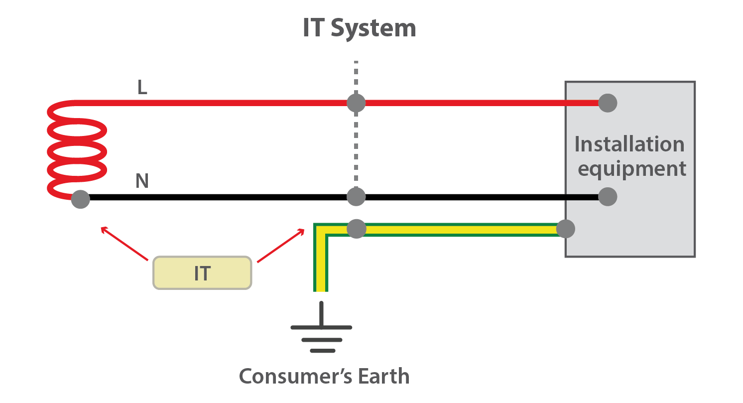
Figure 5–IT System
Implications for PV system earthing
The type of earthing system employed in any country will dictate the kind of earthing system design required for Grid-Connected PV systems; PV systems are treated as a generator (or a source circuit) and need to be earthed as such.
For example, countries employing the use of a TT type earthing arrangement will require a separate earthing pit for both DC and AC sides due to the earthing arrangement. In comparison, in a country where TN-C-S type earthing arrangement is used, simply connecting the PV system to the main earthing bar in the switchboard is enough to meet the requirements of the earthing system.
Various earthing systems exist throughout the world and a good understanding of the different earthing configurations ensures PV systems are earthed appropriately.
Additional resources:
Visit the following sources to learn more about the different types of earthing configuration:
Kamel, RM, 2011. Comparison the Performances of Three Earthing Systems for Micro-Grid Protection during the Grid Connected Mode. Smart Grid and Renewable Energy, [Online]. 2011, 2, 206-215, 206-215. Available at: https://file.scirp.org/pdf/SGRE20110300009_91158972.pdf [Accessed 26 March 2018].
Electrical Installation Guide, 2016. Characteristics of TT, TN and IT systems. [Online] Available at: https://www.electrical-installation.org/enwiki/Characteristics_of_TT,_TN_and_IT_systems. [Accessed 26 March 2018].
United Nations Development Programme, 2016. Earthing and Lightning Overvoltage Protection for PV Plants. [Online] Available at: https://www.lb.undp.org/content/dam/lebanon/docs/Energy%20and%20Environment/DREG/Earthing%20and%20Lightning%20Protection%20for%20PV%20Plants%20Guideline%20Report.pdf [Accessed 26 March 2018].