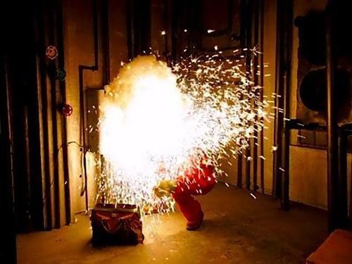
An arc fault is the electrical discharge that occurs between phase to phase or phase to neutral conductors through high impedance plasma discharge, resulting in arc flash. There are several causes of arc flash including, mechanical breakdown, current overload, and human-error (accidental contact with the live wire or energised busbar). An Arc flash is extremely dangerous due to the high temperatures it produces in the surrounding air. In most cases, it could heat up the air close to 20,0000C which could cause fatal burns to anyone in the vicinity of the electrical explosion.
In general, there are two types of arc faults that can occur:
- Series Arc Fault: normally where the cable is partly broken, but the power still continues to flow (e.g. solar modules continuously feeding in the power through a broken cable)
- Parallel Arc Fault: normally occurs between conductors with different voltage levels, jumps between cracks in the insulation of the breakers or exposed conductors resulting in arc fault
Arc faults are extreme electrical events that contain the following characteristics:
- Arc faults can occur in both HV and LV systems. HV arc faults are easier to initiate (due to higher chances of insulation breakdown), have a lower current (kA), and low progression (meaning it has lower chances to spread); whereas in LV circuits, it is harder to initiate, have a higher kA, and high progression.
- They are high impedance faults, as they are crossing an insulating medium.
- Relatively low unsteady current.
- Hard to detect quickly
It’s hard to detect an arc fault quickly, because the arc fault does not fit into a normal breaker trip time-profile. As it is shown in the figure 1, the arcing fault behaves as a short circuit for a few milliseconds (to point 1) and then it drops (to point 2) and slowly increases again (to point 3 or 4 or 5), where it would be then detected by the breaker.
The main point is it would take some time before the arc fault is detected by the protection devices, and by this time a lot of energy has already passed through into the system. This issue, however, could be overcome by setting up proper time profile settings within the safety devices and selecting specific devices to provide safety protection.
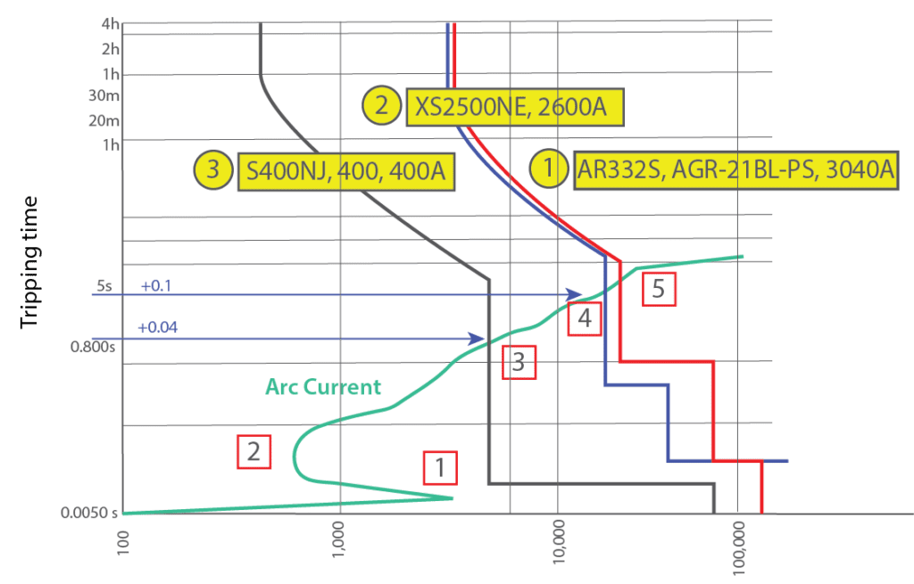
Figure 1: Arc Current on a time-current graph [1]
Calculating Arc Fault Current
The formulas to calculate Arc Fault are found in IEEE standard (IEEE 1584-2018). The formulas are highly dependent on the arrangements of the electrode and voltage of the circuit. Several configurations mentioned in the IEEE standards are VCB (Vertical Conductors/ Electrodes inside a metal box/enclosure), VCBBB (Vertical Conductors /Electrodes terminated in insulating barrier), HCB (Horizontal Conductors/Electrodes in a metal box), VOA (Vertical Conductors/Electrodes in open air, and HOA (Horizontal Conductors/Electrodes in Open Air). More Information on the Configuration could be found in Annex G IEEE 1584:2018.
According to IEEE, the calculation could be divided into the following 2 parts depending on the open-circuit voltage level Voc (AC):
- Model for 600V ≤ Voc (AC)≤ 15000V
- Model for 208V ≤ Voc (AC)≤ 600V
In order to determine the arcing current, there are 2 steps to follow. First is to calculate the intermediate current (average arc fault current at different voltage levels), and then calculate the final value. The intermediate current formula is as the following:

Figure 2: Intermediate average arcing currents [2]
K is the coefficient value which is based on the aforementioned conductor configurations. Different configuration has different values.
The final value for the system with an open circuit Vocin between 600V to 15000V is different with system that has Voc less than 600V. The formulas used to calculate the arc fault energy level for either voltage can be found in IEEE 1584-2018.
Limiting Arc Flash Effects
AS/NZS 3000:2018 Clause 2.5.5.3 provides a simple formula to limit the damaging effects that a switchboard internal arcing can have on the installed equipment. This is referred to as clearing time, which is the upper limit of the breaker interrupt time based upon prospective fault current and the current rating of the switchboard.

Example: If we have a board with a fault level of 15kA, with a full load of 800A. We calculated a clearing time of 0.57s.
0.57s means the breaker interrupt time shall not exceed 0.57s @ 15kA, in order for the arc fault to fit into the breaker time-profile and protect the switchboard. If the breaker settings do not take into account this value, the fault will not be cleared and an arc fault will most likely occur, potentially causing extensive damage to equipment and potentially human life.
Again in AS/NZS 3000:2018 Clause 2.5.5.3, it is also mentioned that the reduction in probability of an arc fault initiation can be obtained by increasing segregation between the busbars inside the switchboard. Switchboard manufacturers usually have different levels of segregation (for example; Form 3B, 4A, and 4B). These Forms relate to different configurations of the busbar inside the switchboard.
As well as circuit breakers, there are many devices that can be used to detect or mitigate the arc fault faster:
- Earth Fault/ Leakage Detection Device: the device detects current on earth instantly and trips the circuit breaker.
- Light Detector (Photosensor): can be implemented inside the switchboard to detect arc light. The downside is it can create nuisance trips when exposed to light.
- Pressure Detection: same concept as light detector. It should be implemented inside the switchboard. The downside is it does not work when the door is open.
- Arc quenching: usually used for high voltage systems. The concept is to create a deliberate three phase fault that can be terminated to replace the arc fault.
Implementation of Arc flash analysis using ETAP® software
Arc flash analysis is carried out for the electrical switchboards in most commercial and industrial facilities for the safety of the personnel working and determining requirements for Personal Protection Equipment (PPE). The ETAP®software package can be used to evaluate the incident energy levels at the switchboard and identify the recommended PPE that an electrician should use when working around the respective switchboard.
The software uses the equations and methodology of IEEE 1584-2018 to calculate the arcing currents, fault clearing times (FCT), incident energy (IE) and arc flash boundary (AFB) at a particular switchboard as shown in Figure 3. Based on these values, the severity of a potential arc fault can be determined. If the resulting values are too high for the site requirements, protective devices and their settings can be manipulated to ensure that such events are mitigated before an arc flash develops.
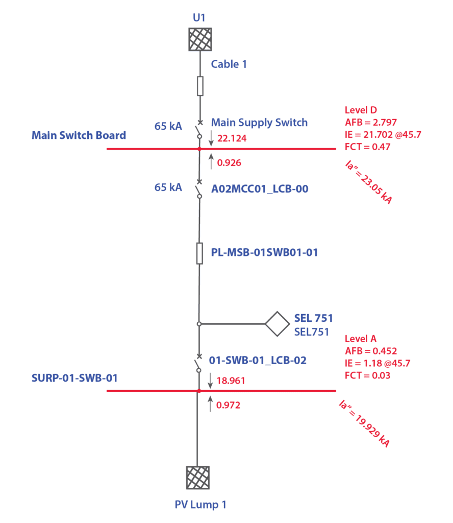
Figure 3: Arc Flash analysis results from ETAP® software.
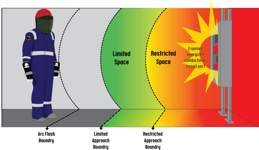
Figure 4: Arc flash boundary
Arc flash hazard labels are generated for each switchboard in a facility to indicate these energy levels and the associated arc flash boundary as shown in Figure 4. PPE such as arc-rated suits and gloves of appropriate ratings can then be used by personnel potentially exposed to these hazards during maintenance work.
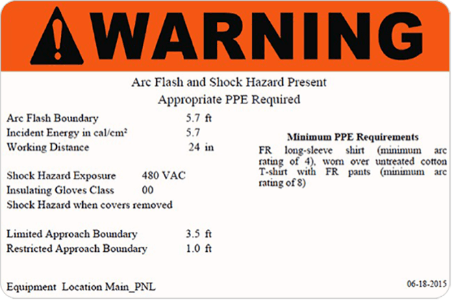
Figure 5: Template of Arc flash label generated in ETAP® software

Figure 6: PPE category level chart
Conclusion
Arc flash is not a common occurrence, but still requires design attention as not determining this accurately can lead to severe damage for equipment and personnel. As a designer or electrical worker, the danger of arc flash can often be overlooked, not only for the system but also for human’s life. Therefore, the main purpose of this article is to show an overview of the dangerous effects of arc flash and how to avoid or mitigate the effects that could happen in our electrical systems.
As knowledge of incident energy levels and degree of arc flash hazard it is essential to generate the arc flash labels for the new switchboards at a facility, arc-flash analysis is carried out prior to connection of a PV system to the grid. As arc flash is a safety hazard, using the correct PPE reduces the risk of injuries and burns to employees and personnel on occurrence of an arc flash incident.
GSES provides design and consultancy services which including the application to connect with various DNSPs throughout Australia. GSES offers services such as protection coordination studies, detailed three-phase and single-phase fault analysis, earth fault studies and arc flash analysis. For more details contact the design team at design@mindaro.energy.
References
| [1] | Nick Thompson, “Arc Flash,” NHP, 2020. |
| [2] | I. S. Association, “IEEE Guide for Performing Arc-Flash Hazard Calculations,” 2018. |
Cover Image Source: Present Group