
For a full overview of the standard update, read our dedicated article here.
The SA TS 5398:2025 key updates for modular battery compliance build on concepts introduced under the Battery Best Practice Guide (BPG), but it introduces more structured requirements that directly affect how battery equipment compliance is assessed, particularly for modular and stackable battery systems.
1. Clearer rules for modular and stackable battery systems
One of the most significant changes is the formal treatment of modular and stackable battery systems under Appendix A.
- TS 5398 sets out structured requirements for battery systems assembled from multiple modules
- Relevant where modules are connected in series or in parallel
- Intent is to remove ambiguity that previously existed under guidance-based approaches
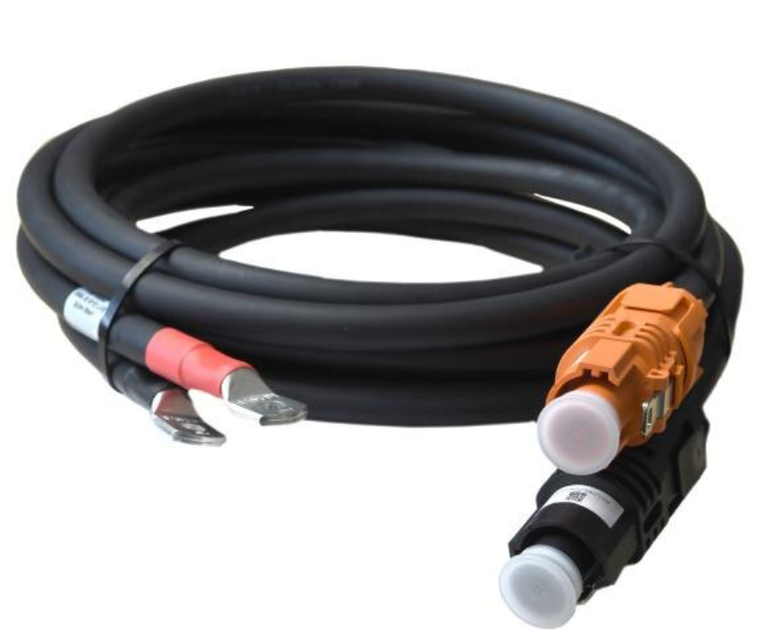
2. Type A vs Type B connector types matter
TS 5398 defines safety requirements based on the connection method of battery modules.
- Type A connectors
- Direct module-to-module plug or socket connections
- Not externally accessible
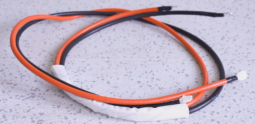
- Type B connectors
- Use externally accessible conductors
- Examples include cables or busbars
These distinctions directly influence how modular systems manage safety risks.
3. Minimum protection requirements for all connectors
Appendix A makes it clear that all connectors between battery modules must meet an IP2X level of protection and ensures the following:
- Live parts are not accessible under normal operating conditions
- Exposure to hazardous voltages is reduced during operation and servicing
Connector type (A or B) then determines how additional safety measures apply, including:
- Isolation requirements: How and where battery modules must be electrically separated
- Overcurrent protection devices (OCPDs): Particularly important for parallel-connected systems
- De-energisation capability: How and when modules must be made safe during maintenance or fault conditions
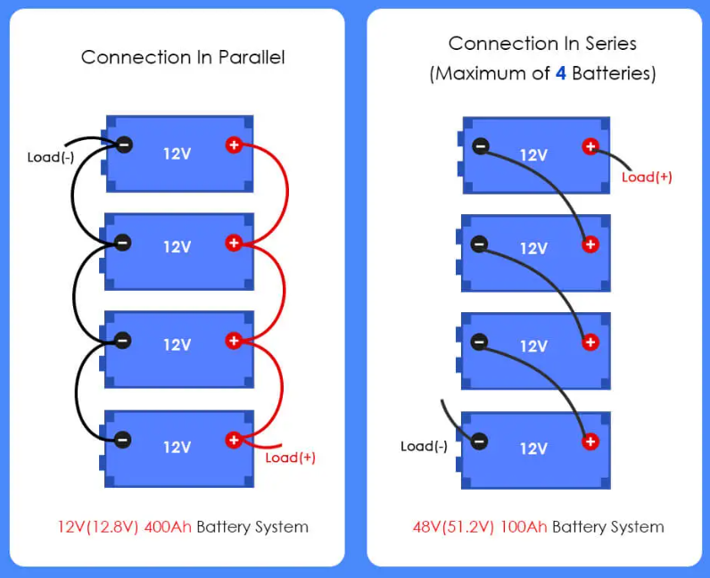
4. TS 5398 applies different requirements to series and parallel configurations
Series-connected battery systems
- Fault current is generally limited to the string current
- Effective isolation is the primary safety focus
- Modules or defined groups of modules must be capable of being safely de-energised
- Appendix A.4.101 reinforces the need for clear isolation (Especially as systems expand or are serviced over time)
Parallel-connected battery systems
- Each module can contribute fault current into a shared fault path
- This significantly increases potential fault current
- Appendix A.4.101 places stronger emphasis on:
- Coordinated use of OCPDs
- Effective isolation arrangements
- Where Type B (externally accessible) connections are used, suitable OCPDs are clearly required to:
- Limit fault current from individual modules
- Prevent cascading faults across the system
This represents a material change for many modular battery designs. Systems that have historically relied primarily on internal electronics, software-based controls, or single-point system isolation may need to be reassessed and, in some cases, updated to align with the clearer expectations set out in Appendix A.4.101, particularly where parallel configurations and externally accessible connections are used.
5. Expanded scope and updated terminology
TS 5398 introduces several broader updates:
- Lead-acid battery systems are now included, recognising their continued use in certain applications
- Terminology has been updated from “master/slave” to “leader/follower”, consistent with Standards Australia language changes
6. Clearer nameplate and marking requirements
Clause 6.2.1.101 introduces more explicit nameplate requirements for electrical energy storage (EES) equipment.
Key requirements include:
- A permanently affixed nameplate
- A single, unique model designation
- Maximum electrical ratings applicable to the installation, which may include:
- d.c. or a.c. Voltage
- d.c. or a.c. Current
- Frequency
- Single-Phase and/or Multi-Phase
These requirements apply to:
- Complete battery systems
- Individual battery modules (where modules form part of the EES equipment)
For leader/follower configurations:
- The leader unit must display the maximum ratings of the complete configuration
- Each follower unit must display the ratings applicable to that individual part
For some products, nameplate changes alone may trigger reassessment or retesting even if the underlying hardware design has not changed.
What The TS 5398 Key Updates Mean and How GSES Can Help
The TS 5398 key updates mark a clear shift toward more structured expectations for modular battery equipment safety. For battery OEMs, importers, and certification bodies, this means that designs, protection strategies, documentation, and even nameplate details that previously aligned with the Battery Best Practice Guide may now require reassessment under Appendix A. In particular, modular systems using parallel configurations or externally accessible connections should be reviewed carefully against the updated isolation and overcurrent protection requirements.
GSES supports industry stakeholders through proper guidance and training aligned with evolving Australian battery safety standards. Our team works closely with manufacturers and industry partners to help understand how TS 5398 applies to specific system designs and prepare for the transition toward a future Australian Standard.
If you’d like to discuss how TS 5398 impacts your battery products, need support interpreting Appendix A, or want to build internal capability through targeted training, contact GSES by phone or email to speak with our team.