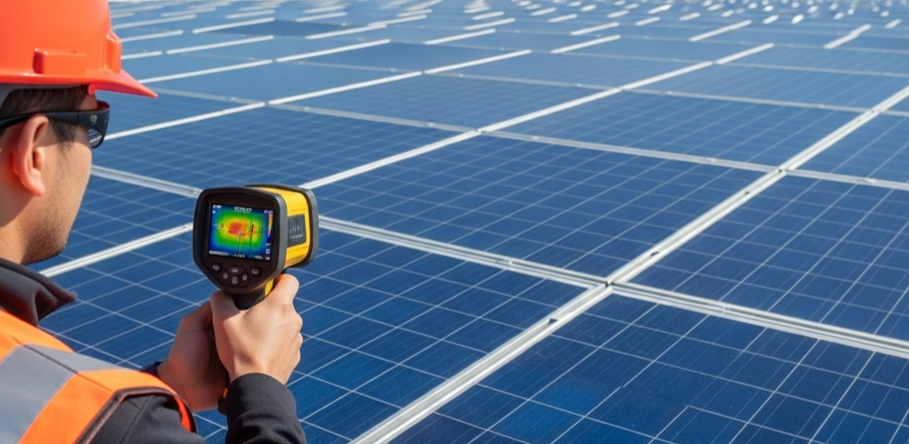
Thermal imaging, also known as infrared imaging, is a powerful diagnostic tool in the inspection of Solar PV systems and Battery Energy Storage Systems (BESS). It captures and visualises temperature variations on a surface, allowing inspectors to identify hot spots, hot joints and irregular heat signatures that could signify electrical faults, failing components, or degraded performance. Because temperature is often the first indicator of electrical failure, thermal imaging offers an opportunity to catch issues before they evolve into safety hazards or costly system failures.
What makes thermal imaging particularly compelling in the Consumer Energy Resources (CER) industry is its unique balance of low-effort and high-value output. A single thermal image can reveal a loose connection, a faulty bypass diode, or an overheating isolator. These faults, if left undetected, can severely impact system safety and performance. Therefore, while the process of capturing thermal data is relatively simple, the insight gained is significant, making thermal imaging a high-value activity.
Seamless Workflow Integration
To ensure thermal imaging remains a low-effort process that doesn’t burden the inspector or disrupt workflow, it’s essential to optimise how thermal data is captured and recorded. There are two critical workflow considerations:
1. Tools and Processes
Inspectors should be equipped with tools that allow them to remain in the workflow without switching platforms or re-organising data offsite. This includes:
- Digital Data Collection Forms: These should be used to record all inspection data. The form must allow image capture directly within individual fields (e.g., disconnection point image field) or support direct upload from the device. Furthermore, the form should be organised to optimise the workflow such that the inspector does not have to move workspaces multiple times or return to the same inspection area multiple times within the same inspection.
- Infrared Camera Integration: Inspectors should use thermal cameras that attach to or integrate with smartphones or tablets. Ideally, the digital forms should allow the direct import of thermal images from these devices.
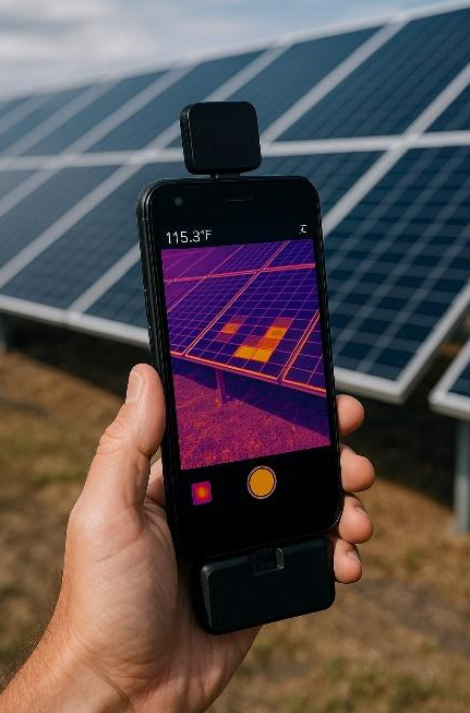
Figure 1 – IR Camera for iPhone
- No Post-Processing Admin Burden: The process should be structured so that no additional effort is required after leaving the site to match thermal images to data fields. This reduces errors, saves time, and increases overall inspection quality.
2. Strategic and Statistically Significant Imaging
The goal of thermal imaging during inspections is to gain maximum insight with minimum additional time on site. To achieve this:
- Balance Thoroughness and Efficiency: Taking a thermal image of every solar module may not be practical. Instead, inspectors should aim for a sample that provides statistical significance without materially increasing inspection time.
- Time Budget Rule of Thumb: Thermal imaging should not add more than 10% to the total time allocated for the inspection as a rule of thumb. Within this window, inspectors should prioritise high-risk areas.
Here are the key specifications to keep in mind when setting up the thermal camera
- Minimum Infrared resolution should be 320×240 as per IEC guidelines.
- The thermal camera should have a thermal sensitivity of less than 0.08°C to ensure accurate detection of defects
- Temperature range for the thermal camera is between -20°C and +150°C to accommodate typical inspection condition.
How to Get the Best Results
- Thermal inspections should be carried out in optimal weather conditions; preferably on clear days with minimal wind and consistent sunlight levels above 600 W/m², as recommended by the IEC TS 62446-3:2017 standard.
- For accurate thermal readings, the camera should be positioned as close to perpendicular to the solar module surface as possible
- Care should be taken to avoid reflections from glass surfaces, as they can distort thermal readings and lead to inaccurate results
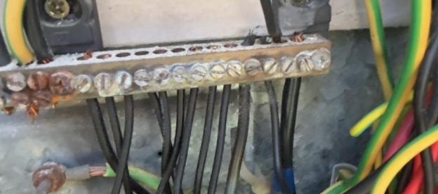
- Targeted Focus Areas: Inspect key electrical junctions, such as:
- Disconnection points
- Isolators (both DC and AC)
- Inverter connections
- Combiner boxes
- Strategically segmented panel arrays
- PV Distribution Boards
- Main Switch Boards

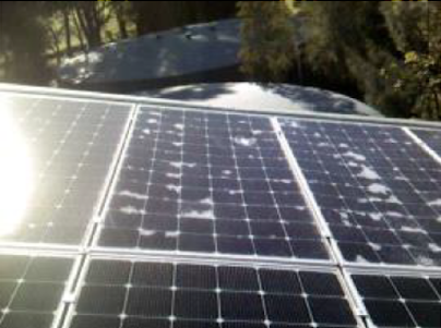
Figure 2 – Thermal Image Search Space for Large Array
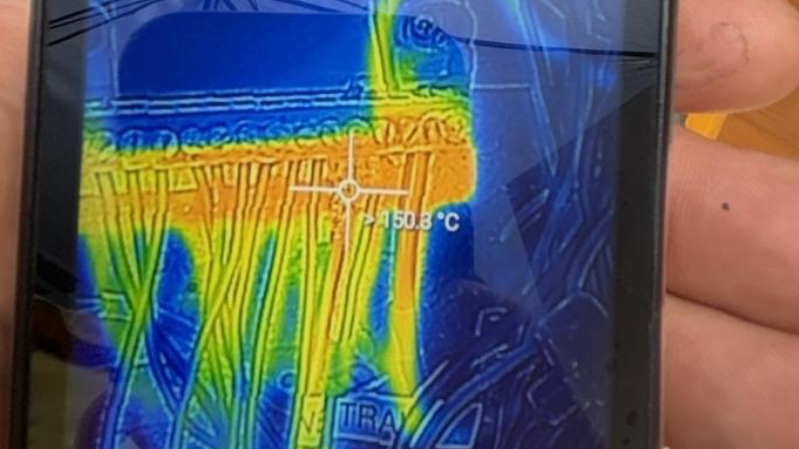
- Use Adaptive Imaging Strategy: If a thermal anomaly is identified, inspectors should focus further on the affected area using a half-interval search strategy or similar method to narrow down the root cause. In addition, many thermal cameras will allow the user to select specific areas of the image to create a more granular contract of thermal distribution.
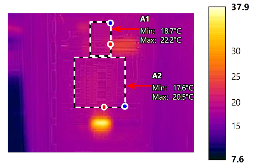
Figure 3 – Thermal Search Space

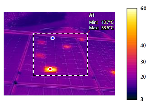
Figure 4 – Thermograph of Search Space A1
Understanding Thermal Images and Thresholds of Concern
A thermal image shows surface temperatures as a gradient, allowing comparison of thermal behaviour across components. Key indicators include:
- Uniformity: Modules or connections should display consistent temperature profiles.
- Hot Spots: An area with significantly higher temperature may indicate electrical resistance or failure.
- Temperature Differential: Large temperature imbalances (>10°C) between similar components in the same conditions should be flagged.

When to Raise Concern:
- Report and Monitor: When temperatures exceed typical variation but remain within manufacturer tolerances.
- Elevate Concern: When temperatures approach or exceed rated limits, particularly at electrical connections or components with a history of failure (e.g., DC isolators).
Should Components Be Opened for Imaging?
Yes. Comprehensive thermal imaging inspections should include internal imaging where safe and practical. This includes:
- DC Isolators
- Inverter Internal Terminals (with covers removed)
- Escutcheon Panels
- Disconnection Points
These activities should be conducted as part of a standard inspection workflow, particularly when voltage or current checks are already being performed. Since these checks require opening equipment, it is efficient and practical to perform thermal imaging concurrently.
Conclusion
Thermal imaging is an essential, high-yield addition to the Solar PV Systems and Battery Energy Storage System (BESS) inspection process. When implemented correctly, with well-integrated tools and efficient strategies, it enables early fault detection with minimal added effort. By streamlining image capture, targeting high-risk areas, and embedding thermal checks into standard workflows, inspectors can deliver exceptional value in safety, performance, and asset longevity for solar PV systems.
Are you a technician looking to gain insight into inspection best practices for grid-connected PV systems?
Our upcoming Inspection of Grid-Connected Systems course is designed just for you. Stay tuned!
Want expert support with your solar PV or battery system inspections? Get in touch with our team today.