Due to the high level of distributed, grid-connected PV systems in Australia, there is concern over grid stability and safety risk posed by inverter generation systems. The current inverter connection standard, AS4777.1:2016, which came into effect in April this year, reflects these sentiments by mandating that commercial PV systems use central protection, more popularly referred to as secondary mains protection.
Central Protection is a device, or a collective of devices, which provides protection functions for inverters and the grid, external to the inverter’s in-built protection functions. The additional requirement for central protection is essential to minimize the impacts of fluctuations in voltage, frequency and other parameters on the electrical grid. Central protection also helps prevent damage to the PV system caused by grid fluctuations, ensure a safe, balanced distribution network, maintain reliability of the grid and help the grid with increased penetration of distributed
generation systems.
When is central protection needed?
AS/NZS 4777.1 :2016 specifies central protection as a requirement for systems with a capacity above 30kVA capacity on a 3-phase network. The local Distribution Network Service Providers (DNSPs) may have their own system size limits as per their specific network conditions. This is generally intimated to the system designer at the time of application to connect.
Central Protection is therefore essential for most commercial PV systems for compliance with both AS/NZS 4777.1 :2016 and the requirements set by the DNSPs.
Central protection parameters and specification as per AS/NZS 4777.1:2016
AS/NZS 4777.1: 2016 clause 3.4.4 states that central protection shall be installed to performed the following functions-
- Coordinate multiple IES installations at the one site.
- Provide protection for the entire IES installation.
- Provide islanding protection to the connected grid.
- Preserve safety of grid personnel and the general public.
The location of the central protection shall be placed as close to the main switch (grid supply) of the installation as practicable. Figure 1 below shows the location of the central protection relay and its location with reference to the Main switchboard.
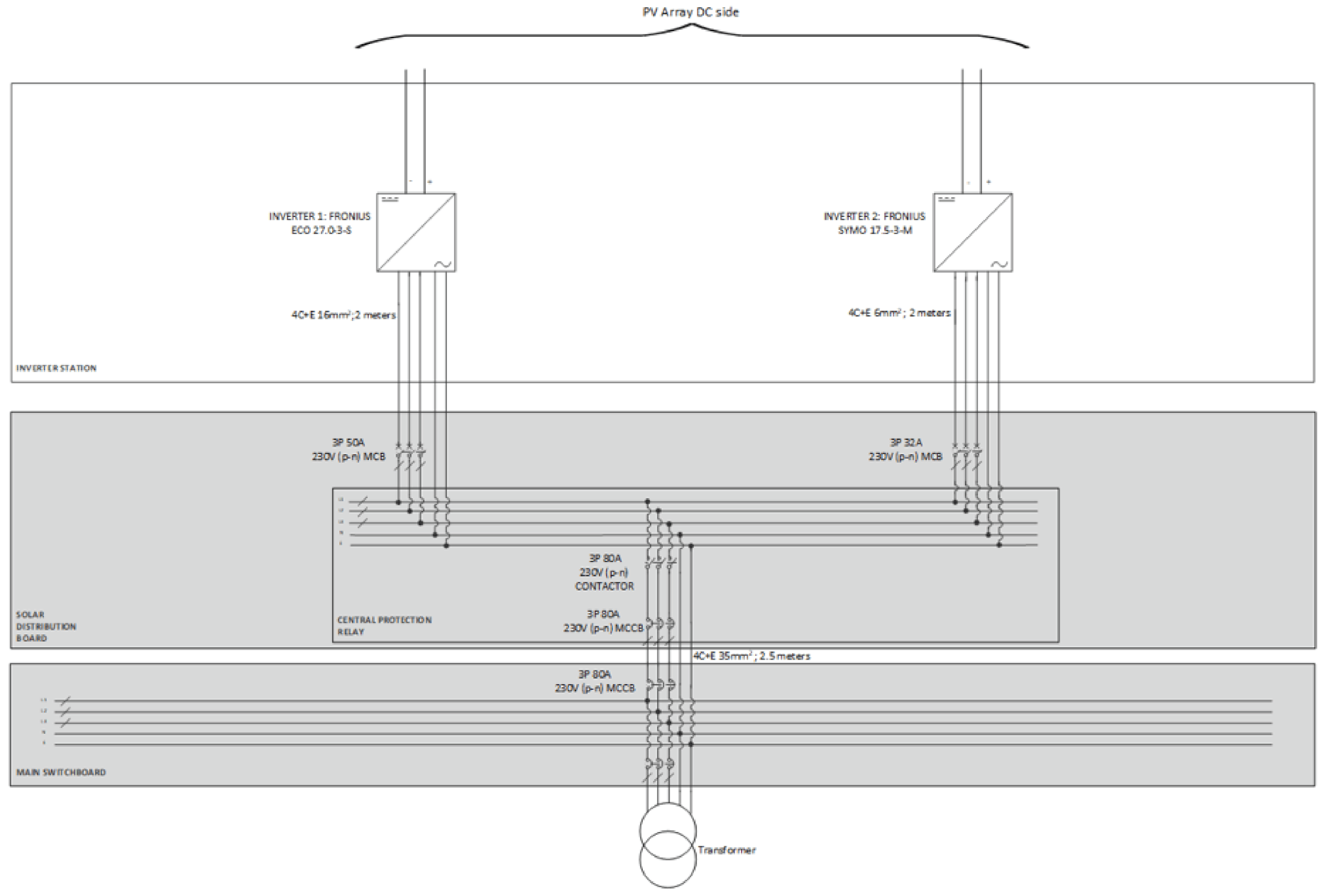
Figure 1 Example of central protection relay location
The voltage and frequency set points as defined by the AS/NZS 4777.1 standard are given below in Table 1-
Table 1: Central Voltage and Frequency protection set points as defined by AS/NZS 4777.1:2016
| Setting Parameter | Disconnection time | Parameter value |
| Sustained over voltage (V>) (based on average value over a 10-min period) | 15 seconds | 255 V |
| Over voltage (V>) | 2 seconds | 260 V |
| Under voltage (V<) | 2 seconds | 180 V |
| Over frequency (f>) | 2 seconds | 52 Hz |
| Under frequency (f<) | 2 seconds | 47 Hz |
Please note that the central protection parameters for voltages and frequencies defined in AS/NZS4777.1:2016 can be adjusted by the DNSPs around the country for their specific network requirements.
Central protection device characteristics and ANSI device codes
Devices which offer central protection functions come with an array of functions. Choice between the central protection devices is dictated by their compliance to the standard and the DNSP’s requirements. Most devices are capable of under/over voltage and under/over frequency detection requirements as a minimum. However, DNSPs may specify additional functional requirements.
The heart of a central protection device, the sensing relay, also referred to as the secondary mains relay, can either be purely voltage based and negating the need for additional CTs, or both voltage and current based, requiring additional CTs and allows the device to monitor more parameters. The ANSI (American National Standards Institute) device code is used as a reference to identify the parameters which are monitored by a central protection solution.
Some solutions may also offer communications capabilities such as RS485, GPRS or ethernet, which enables the parameters observed to be viewed with other control systems such as SCADA.
Table 2 below shows some common requirements specified by the DNSPs and their corresponding ANSI device codes. Note that the last three items, while specified by DNSPs, do not appear in AS/NZS4777.1 as requirements.
| Parameter | ANSI device code |
| Over Voltage | 59 |
| Under Voltage | 27 |
| Over Frequency | 81H |
| Under Frequency | 81L |
| Vector Shift | 78 |
| ROCOF (Rate of Change of Frequency) | 81R |
| NVD (Neutral Voltage Displacement) | 59N |
| Phase Balance Current (Current unbalance) | 46 |
Over voltage (ANSI device code 59) and Under voltage (ANSI device code 27)
In over/under voltage protection, the measured voltage signal (RMS value) is compared with the pre-defined set point value that is programmed in the relay. If the voltage is outside the pre-defined set point value for a pre-defined set duration then a signal will trip the relay, which then trips the contactor (or circuit breaker) that opens the circuit.
Typically, a voltage hysteresis is designed into the circuit to prevent any unwanted rapid switching caused by voltage oscillation around the overvoltage and undervoltage limits. This means that for an overvoltage scenario, the voltage must decrease under the hysteresis limit to clear the fault. Similarly, for an undervoltage scenario the voltage must exceed the hysteresis limit to clear the fault. Figure 2 and 3 below shows the hysteresis curves.
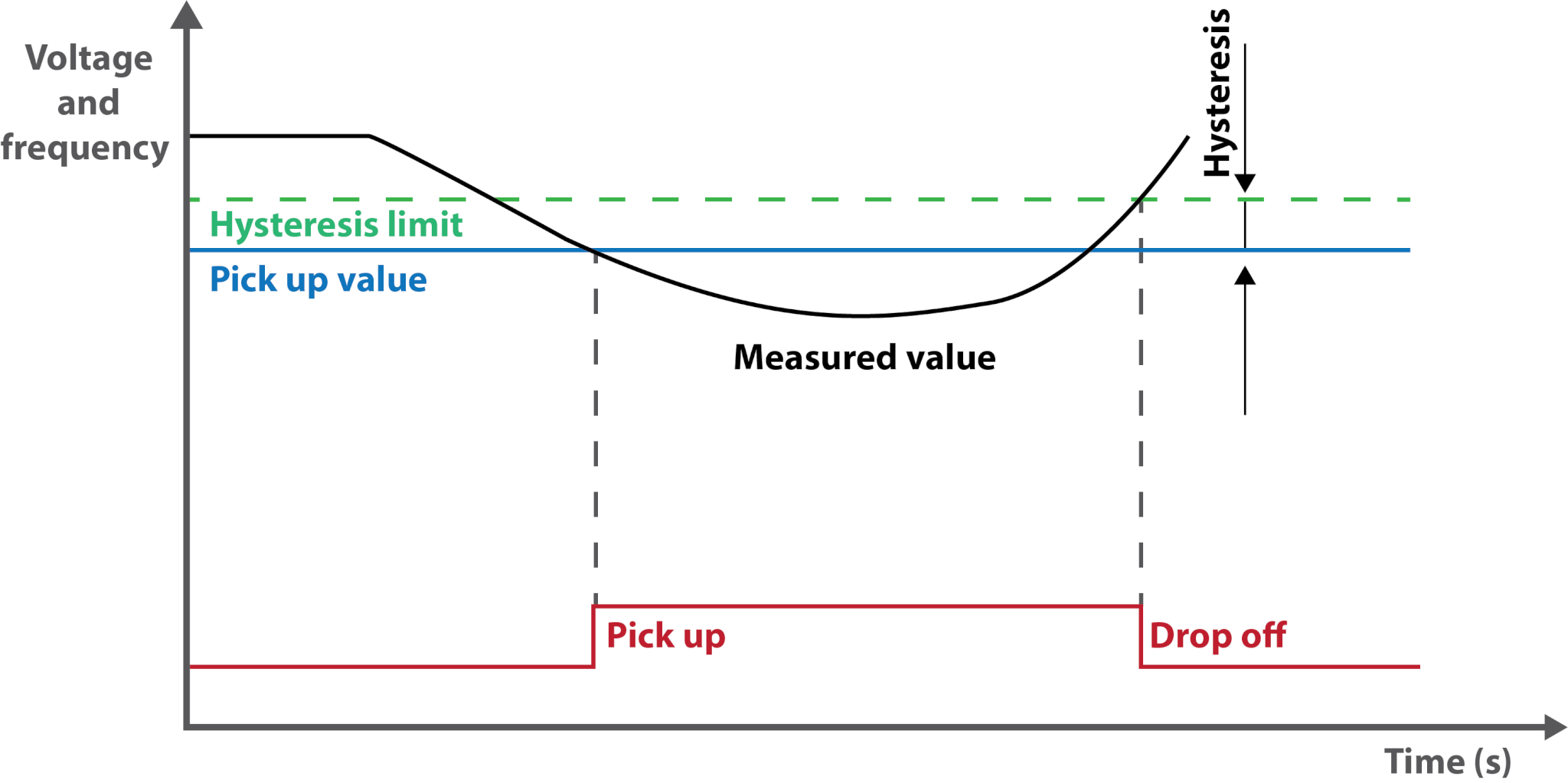 Figure 2: Overvoltage and Over Frequency Hysteresis
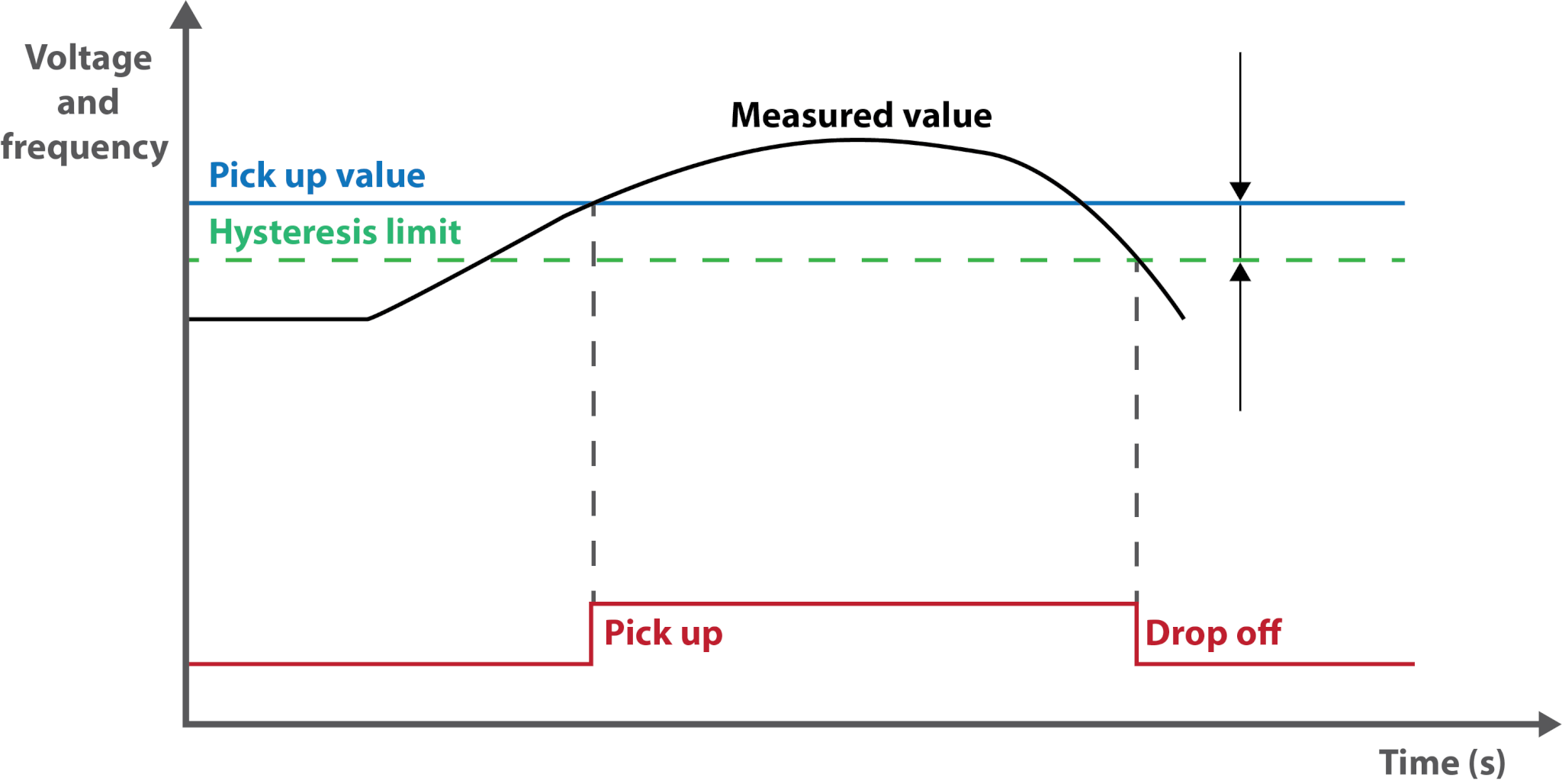 Figure 3: Under voltage and Under Frequency Hysteresis
Over frequency (ANSI device code 81H) and Under frequency (ANSI device code 81L)
To provide over and under frequency protection, the frequency value measured on the red phase (of the three phases present) is compared with the pre-defined set point value of over frequency or under frequency that is programmed in the relay. If the frequency is outside the pre-defined set point value for a pre-defined set duration then a signal will trip the relay, which then trips the contactor that opens the circuit.
Similar to over and under voltage protection, a frequency hysteresis is set to prevent unwanted rapid switching caused by frequency oscillation around the over frequency and under frequency limits. For an over-frequency scenario, the frequency must decrease under the hysteresis limit to clear the fault. Similarly, for an under-frequency scenario the frequency must exceed the hysteresis limit to clear the fault. Figure 2 and 3 above shows the hysteresis curves.
Vector Shift (ANSI device code 78):
Vector shift is a type of Loss of Mains function which detects the instantaneous changes in three phase voltage angles which occur when the main grid is lost. This observation is based on the principle of the displacement phase angle difference, which is the difference in the angle between the voltage at the terminals during the presence of load (VL) and the internal voltage during no load (VS) in a Grid-Connected PV system.
In the vector shift algorithm, a measurement is taken from each of 3 phase voltages after every half cycle and a decision is made by the relay after every full cycle. The difference in angle is calculated from zero crossing times between the current and previous cycle. The obtained 6 samples (2 half cycles x 3 phase voltages) are compared with the results from the previous cycle and if 5 of those 6 results observe a displacement phase angle difference (∆θ) above the setting threshold, a trip signal is initiated. Since the vector shift algorithm is a comparative algorithm, the decision making and tripping time is approximately 30ms. The use of three phase makes the algorithm more resistant to harmonic distortion, interference, imbalanced faults and also decreases the false tripping during non-symmetrical faults. Figure 4 shows the displacement angle during loss of mains signal.
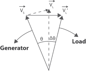
Figure 4: Change in the displacement angle during loss of mains event Dotted line shows vector operation during normal operation, solid line shows vector operation during loss of mains, ∆θ is measured to evaluate whether loss of mains has occurred.
ROCOF (ANSI device code 81R):
In electrical engineering, rate of change of frequency (ROCOF) is based on the principle of imbalance caused by input mechanical power and load. As this imbalance occurs after the disconnection from main grid, the frequency changes dynamically, even in grid-connected PV systems. This change in frequency is expressed as tangent in time (Hz/s). If the absolute value of the tangent exceeds the pre-determined pick up value, a trip signal to the relay is initiated.
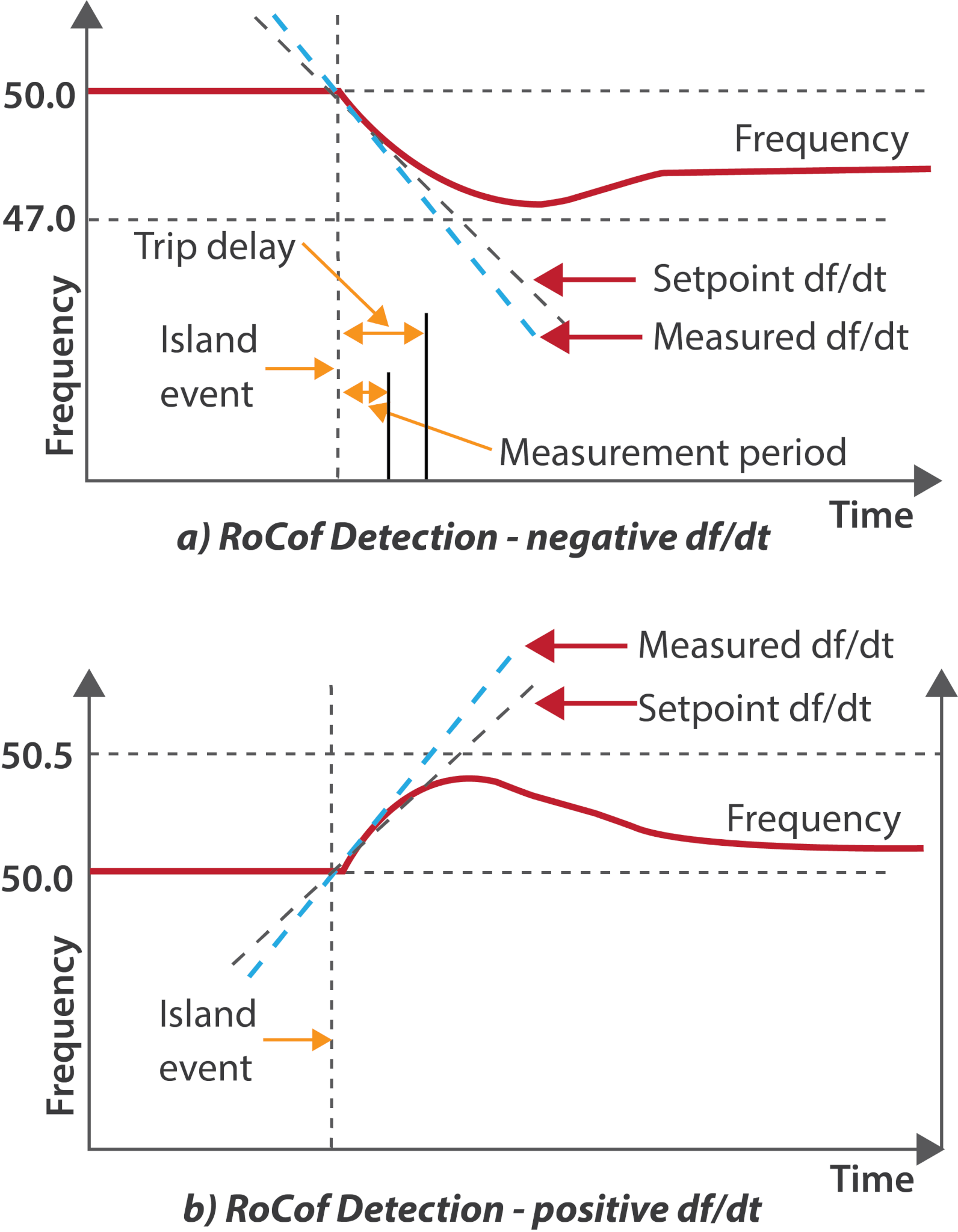
Figure 5: ROCOF graphs for both positive and negative changes to frequencies with reference to time
NVD (Neutral Voltage Displacement) protection (ANSI device code 59N):
This type of protection is generally required in medium or high voltage systems with isolated or indirectly earthed neutrals (Typically Delta -Star configuration). This may be required by the DNSP for Grid-Connected PV systems depending on the system size and local network conditions.
Under the normal balanced three phase operation, the sum of three phase to earth voltages, that is, the neutral voltage, should equal zero. Due to the system being isolated/indirectly earthed, when an earth fault occurs, the fault facilitates the connection of one phase with earth, which poses a threat to the system safety. This fault also causes the neutral voltage to rise. This is called the neutral voltage displacement (NVD).
Where NVD has been detected, the protection relay can clear the fault by generating the appropriate trip signal. In some cases, the NVD doesn’t detect the fault location and is used for providing an earth fault alarm. Also, it is important to make sure that the voltage transformers are of the appropriate type and that they are properly configured for NVD protection.
Phase Balance Current (Current unbalance) (ANSI device code 46):
A phase balance current relay detects the phase loss or unbalance in the generators. It is used to avoid unbalanced loads at the point of mains connection. To ensure compliance to ANSI 46, current transformers should be installed on the main switchboard side to measure the amount of unbalance and whether it is within the threshold.
Conclusion
Central protection offers protection to the grid and the installed system by monitoring various parameters and ensure that the PV system only operate within the set parameters.
The correct installation of central protection to DNSP specifications will prevent damage to the PV system caused by grid fluctuations, ensure safe balanced distribution network, maintain reliability of the grid and help the grid with more penetration of distributed generation systems.